
User Manual

1397 150HP AC Line Disconnect
5
1397-5.21 July, 1997
GRD
A1
45
P4
P4
P4
S
4
S
4
S
4
Disc.
Panel
Retaining
Screw
Disc.
Panel
Retaining
Screw
Disc.
Panel
Retaining
Screw
Disc.
Panel
Tab
Screw
Disc.
Panel
Tab
Screw
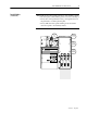
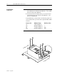
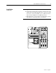
Installation
(continued)
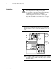
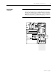
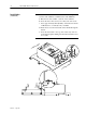
❐
5
Install the disconnect panel in the front of the auxiliary chassis
enclosure in place of the auxiliary panel cover removed in Step 2.
• The (2) disconnect panel tab screws go through the holes in
the panel tabs to lock the panel in place.
• The (3) M6 disconnect panel retaining screws attach the
disconnect panel to the auxiliary chassis.