
User guide


Publication 1395-RTP-5.1 - September 1997
3-4 Start-Up Instructions
Connect hand held programming terminal to Drive at DHT
Connector, located to the left of TB3 at the bottom of the Drive. Upon
power-up, communications are initialized as indicated by the letter I
in Drive graphically displaying a moving pendulum.
Check LEDs on Digital Reference Adapter Board for +12V, -12V,
+5V, and +24V Status. (See Troubleshooting section for further
explanation.)
Verify links and parameters match the tables provided using the
Programmable Terminal. To access links, enter “Drive Set Up” mode,
select “Read Edit”, and view the next link each time the “ENTER”
key is depressed. If necessary, parameters and links can be entered
with the DHT or the Intelligent Terminal System, (ITS), if available
or Drive Tools software.
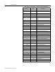
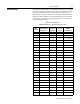
The following Parameter list is a quick reference table showing the
set-up parameters and values associated with an RTP start-up. (The
motor data is for G.E. and Baldor Motors, refer to proper – 18
drawings for other motors). Refer to Bulletin 1395 Drive Installation
& Maintenance Manual or associated schematics for complete
Parameter list and descriptions.
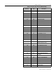
Table 1: Link List
Parameter Links
Sink Source
450 TO 100
151 TO 400
152 TO 200
153 TO 404
154 TO 403
161 TO 407
163 TO 405
164 TO 408
165 TO 410
166 TO 411
250 TO 100