Allen-Bradley Reel Tension Paster Adapter (Bulletin 1395) User Manual
Important User Information Because of the variety of uses for the products described in this publication, those responsible for the application and use of this control equipment must satisfy themselves that all necessary steps have been taken to assure that each application and use meets all performance and safety requirements, including any applicable laws, regulations, codes and standards.
Table of Contents Preface Who Should Use This Manual . . . . . . . . . . . . . . . . . . . . . . Purpose of This Manual . . . . . . . . . . . . . . . . . . . . . . . . . . . Safety Precautions . . . . . . . . . . . . . . . . . . . . . . . . . . . . . . . Contents of This Manaul. . . . . . . . . . . . . . . . . . . . . . . . . . . Related Documentation . . . . . . . . . . . . . . . . . . . . . . . . . . . Common Techniques Used in This Manual . . . . . . . . . . . . Product Receiving. . . . . . . . . . . .
Table of Contents This page intentionally left blank. Publication 1395-RTP-5.
Preface Preface Read this preface to familiarize yourself with the rest of the manual. This preface covers the following topics: Who Should Use This Manual • who should use this manual • the purpose of this manual • safety precautions • contents of this manual • related documentation • conventions used in this manual • product receiving • Allen-Bradley support Use this manual if you are responsible for installing an Allen-Bradley 1395 Reel Tension Paster (RTP) Drive.
P-2 Preface Safety Precautions The following general precautions apply to Bulletin 1395 Drives and to RTP applications: ! ATTENTION: Only those familiar with the RTP system, the products used in the system, and the associated machinery should plan or implement the installation, startup, and future maintenance of the system. Failure to comply can result in personal injury and/or equipment damage.
Preface ! P-3 ATTENTION: This Drive system contains ESD (electrostatic discharge) sensitive parts and assemblies. Static control precautions are required when installing, testing, or repairing this assembly. Component damage can result if ESD control procedures are not followed. If you are not familiar with static control procedures, refer to Allen-Bradley publication 8000-4.5.2, Guarding Against Electrostatic Damage or any other applicable ESD protection handbook.
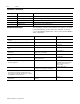
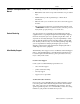
P-4 Preface Contents of This Manual Chapter Title Contents Preface Purpose, background, and scope of this manual 1 Drive Description Description of equipment and specifications 2 Description of Operation Drive system modes and the global RTP 3 Start-Up Instructions Terminology, parameter set-up and configurations 4 Troubleshooting Digital reference adapter fault messages Related Documentation The following documents contain additional information concerning related Allen-Bradley products
Preface Common Techniques Used in This Manual P-5 The following conventions are used throughout this manual: • Bulleted lists such as this one provide information, not procedural steps. • Numbered lists provide sequential steps or hierarchical information. • When we refer you to another location, the section name appears in italics.
P-6 Preface This page intentionally left blank. Publication 1395-RTP-5.
Chapter 1 Drive Description Drive System The Drive System is designed to utilize tension feedback from an Unwind Dancer to regulate paper roll tension, allowing for continuous, non-stop pasting of the new roll to the existing web. Controller The Drive System utilizes a Bulletin 1395 microprocessor based Drive to control the speed and torque of the associated motor.
2 Drive Description This page intentionally left blank. Publication 1395-RTP-5.
Chapter 2 Description of Operation Drive System The RTP Drive utilizes a three phase, armature regeneration, digital DC Bulletin 1395 Drive to control the DC motor in a surface driven unwind. The speed demand for the Unwind Drive is generated from press speed via a zero speed magnetic pickup. In normal operation, the press speed reference is trimmed by dancer position error to maintain constant dancer position.
2-2 Description of Operation The press speed is measured with a magnetic pickup and fed into the Digital Reference Adapter Board on the Drive. This signal serves as the basic speed reference for the unwind belts. The press speed signal is linked to the Drive Velocity Reference (Parameters 153 and 154) and sent through the Drive Ramp Control. The dancer input is fed into the analog input channel on the Drive and linked to the Process Trim Reference (Parameter 161) and sent through the Process Trim Control.
Description of Operation 2-3 When the belts have accelerated to line speed, the up-to-speed algorithm in the Drive energizes the “Speed Match” output. The belts should be fully down on the new roll before the accelerate mode is initiated. When the “Speed Match” signal is present the new roll is ready to splice. Mode 5 SPEED MATCH (The new roll is spliced in and the belt Drive system returns to Mode 1.
2-4 Description of Operation Mode 8 AUTO SLACK, WEB LOOSE With the “Auto Slack” signal present, the web out detector is de-energized when the dancer reaches full position and the web becomes fully slack. This sets the torque reference to zero which will allow the motor to free-wheel, (no armature current or torque) but keeps the Drive energized. The normal exit from Mode 8 is back to Mode 7 via the Dancer reaching mid-position unless both inputs DI2 and DI7 are low, in which case, Mode 8 exits to Mode 11.
Description of Operation 2-5 Mode 11 REGENERATIVE STOP This mode is entered if Drive Permit drops out during any of the Modes 1 to 5. This mode is also entered when exiting Mode 8 (Auto Slack,Web Loose), Mode 9 (Reverse Run, Dancer High) and Mode 14 (Reverse Run, Dancer Center). This stops the roll by sending the controller into a regenerative stop. Configuration Parameter 572, Bit 2 will determine if Drive will go into a full regen stop or a ramped regen stop. Refer to Logic State Diagrams.
2-6 Description of Operation Mode 21 LINE SPEED REFERENCE When the Drive is in a normal run (Mode 1) or accel cycle (Mode 4), the Drive will follow the press speed reference. Mode 22 PRESET 1 SPEED REFERENCE When the Drive is in auto slack with the web tight (Mode 7), the Drive will follow the Preset 1 speed reference. This is a low forward speed reference which is adjustable in Drive Parameter 633.
Description of Operation 2-7 Mode 27 PROCESS TRIM ENABLE This enables the process trim in the Drive to allow proper tensioning of the web. Movement of the dancer will either add or subtract from the press speed reference in order to hold the dancer close to the center position at all times during normal run.
2-8 Description of Operation Mode 30 EMULATE SPEED REFERENCE (ESR) – Europe The speed reference to the Drive will be one of the following: • The press line speed, which enters the Drive at the Digital Reference input of the DRA board. • A preset speed for Auto-Slack and Run Reverse Dancer High (RRDH) (Slack Remove). Refer to the State Logic Diagram in the system binder. • An “Emulated” line speed from a potentiometer.
Chapter 3 Start-Up Instructions Introduction The following start-up instructions should be used to fine tune the operation of the RTP Drive. The complete start-up procedure for the associated Drive can be found in the Bulletin 1395 Installation and Maintenance Manual. Read and understand the complete procedure prior to attempting start-up of the RTP Drive. Important: Before attempting to operate the Drive, ensure that the mechanics of the associated press system have been checked and properly set up.
3-2 Start-Up Instructions Configuration Parameter Parameter whose value may be changed during normal operation of the Drive. The Configuration Parameters are used to input reference and feedback information to the Drive, and to provide monitoring points for control signals. The Configuration Parameters are one of two types, termed Source or Sink Parameters. Refer to the Bulletin 1395 Installation and Maintenance manual for detailed description of Source and Sink Parameters.
Start-Up Instructions 3-3 ITS (Download) To download from ITS to Drive: From Main Menu, Select “Drive Data”, Select “Edit” ENTER key, Select “Parameter”, (cursor through Parameters), make changes, ESC, Select “EEPROM”, ENTER key, Select “Save”, ENTER key DHT (Hand-Held Programming Terminal) From Main Menu, Select “Parameters”, Type Parameter number, ENTER key, Arrow-down cursor to value and type new value, ENTER key, When changes are completed, depress “MENU” key, The DHT will prompt “SAVE CHANGES”? Sele
3-4 Start-Up Instructions Connect hand held programming terminal to Drive at DHT Connector, located to the left of TB3 at the bottom of the Drive. Upon power-up, communications are initialized as indicated by the letter I in Drive graphically displaying a moving pendulum. Check LEDs on Digital Reference Adapter Board for +12V, -12V, +5V, and +24V Status. (See Troubleshooting section for further explanation.) Verify links and parameters match the tables provided using the Programmable Terminal.
Start-Up Instructions 3-5 Table 2: Parameter List, Factory (Initial) Settings Parameter * Value Description 551 0.0 ANALOG OFFSET #1 553 0.
3-6 Start-Up Instructions Table 2: Parameter List, Factory (Initial) Settings (Continued) Parameter Value Description 651 20 ACCEL TIME 652 10 DECEL TIME 659 400 KI VELOCITY LOOP 660 150 KP VELOCITY LOOP 661 65535 KF VELOCITY LOOP 663 150 FORWARD BRIDGE CURRENT LIMIT 664 150 REVERSE BRIDGE CURRENT LIMIT 713 0 PROCESS TRIM FILTER 714 0 INTEGRAL PRELOAD 715 0 KI INTEGRAL GAIN 716 4096 KP PROPORTIONAL GAIN 717 -165 PROCESS TRIM LOW LIMIT 718 165 PROCESS TRIM HIGH LIMI
Start-Up Instructions Control Boards 3-7 Main Control Board (A8) – Figure 3-1 illustrates the major hardware points on the board. The board performs all control functions of the Bulletin 1395 Drive. Hardware located on the board is used to support operation of the microprocessor program. The primary functions performed include: • Microbus Interface • Control Firmware • Analog Signal Interface • Develop gate control signals sent to the Power Stage Interface Publication 1395-RTP-5.
3-8 Start-Up Instructions Figure 3.1 Main Control Board Overview Publication 1395-RTP-5.
Start-Up Instructions Cross Reference 3-9 The printing diameter Tables 3 through 6 provide the proper tracking information such as the number of gear teeth for the magnetic pickup gear, the maximum belt motor speed and the press shaft speed at maximum press impressions per hour. The main tracking Parameter (Parameter 562) should be set at the maximum press shaft speed that corresponds to the maximum press impressions per hour. The value used for default is 2566.
3-10 Start-Up Instructions Table 3: Cross Reference (Printing Diameter = 14-1/32; Gear Teeth = 131) (Continued) Publication 1395-RTP-5.1 - September 1997 IMP/ HOUR RTP PRESS SPD. SENSOR FREQ (HZ) 40000 2911.11 42000 WEB VELOCITY (FT/MIN) BELT MOTOR RPM PRESS DRIVE SHAFT RPM 1224.45 831.99 1333.33 3056.66 1285.67 873.59 1400.00 44000 3202.22 1346.90 915.19 1466.67 46000 3347.77 1408.12 956.79 1533.33 48000 3493.33 1469.34 998.39 1600.00 50000 3638.89 1530.56 1039.
Start-Up Instructions 3-11 Table 4: Cross Reference (Printing Diameter = 14-1/2; Gear Teeth = 135) IMP/ HOUR RTP PRESS SPD. SENSOR FREQ (HZ) WEB VELOCITY (FT/MIN) BELT MOTOR RPM PRESS DRIVE SHAFT RPM 100 7.50 3.16 2.14 3.33 400 30.00 12.65 8.57 13.33 600 45.00 18.98 12.86 20.00 800 60.00 25.31 17.15 26.67 1000 75.00 31.63 21.43 33.33 1200 90.00 37.96 25.72 40.00 2000 150.00 63.27 42.87 66.67 4000 300.00 126.54 85.74 133.33 6000 450.00 189.80 128.61 200.
3-12 Start-Up Instructions Table 4: Cross Reference (Printing Diameter = 14-1/2; Gear Teeth = 135) (Continued) IMP/ HOUR RTP PRESS SPD. SENSOR FREQ (HZ) WEB VELOCITY (FT/MIN) BELT MOTOR RPM PRESS DRIVE SHAFT RPM 50000 3750.00 1581.70 1071.75 1666.67 52000 3900.00 1644.96 1114.62 1733.33 54000 4050.00 1708.23 1157.49 1800.00 56000 4200.00 1771.50 1200.36 1866.66 58000 4350.00 1834.77 1243.23 1933.33 60000 4500.00 1898.04 1286.10 2000.00 62000 4650.00 1961.30 1328.
Start-Up Instructions 3-13 Table 5: Cross Reference (Printing Diameter = 13-11/16; Gear Teeth = 128) (Continued) RTP PRESS SPD. SENSOR FREQ (HZ) WEB VELOCITY (FT/MIN) BELT MOTOR RPM 6000 426.67 179.17 121.94 200.00 8000 568.89 238.89 162.59 266.67 10000 711.11 298.61 203.24 333.33 12000 853.33 358.34 243.88 400.00 14000 995.55 418.06 284.53 466.67 16000 1137.78 477.78 325.18 533.33 18000 1280.00 537.50 365.82 600.00 20000 1422.22 597.23 406.47 666.67 22000 1564.
3-14 Start-Up Instructions Table 5: Cross Reference (Printing Diameter = 13-11/16; Gear Teeth = 128) (Continued) IMP/ HOUR RTP PRESS SPD. SENSOR FREQ (HZ) WEB VELOCITY (FT/MIN) BELT MOTOR RPM PRESS DRIVE SHAFT RPM 60000 4266.66 1791.68 1219.41 2000.00 62000 4408.88 1851.40 1260.06 2066.66 64000 4551.11 1911.13 1300.71 2133.33 66000 4693.33 1970.85 1341.35 2200.00 68000 4835.55 2030.57 1382.00 2266.66 70000 4977.77 2090.29 1422.65 2333.33 72000 5119.99 2150.02 1463.
Start-Up Instructions 3-15 Table 6: Cross Reference (Printing Diameter = 15; Gear Teeth = 140) (Continued) IMP/ HOUR RTP PRESS SPD. SENSOR FREQ (HZ) WEB VELOCITY (FT/MIN) BELT MOTOR RPM 20000 555.56 654.50 444.58 666.67 22000 1711.11 719.94 489.04 733.33 24000 1866.67 785.39 533 49 800.00 26000 2022.22 850.84 577.95 866.67 28000 2177.78 916.29 622.41 933.33 30000 2333.33 981.74 666.87 1000.00 32000 2488.89 1047.19 711.32 1066.67 34000 2644.44 1112.64 755.78 1133.
3-16 Start-Up Instructions Speed Match The Drive is set up at the factory to ensure an accurate speed match between the new roll coming up to speed and the existing web. This is accomplished by using the at set speed algorithm in the Drive. The up to speed tolerance (Parameter 709) sets the hysteresis in motor RPM around the at speed point. When the new roll is speed matched with the press speed reference, and the motor is not at zero speed, the Drive will go into Mode 5 which is speed match.
Start-Up Instructions 3-17 2. Once step 1 is complete, the dancer should be allowed to move freely. Move the dancer up and down to make sure there is no mechanical binding. Then move the dancer to the approximate position of “WEB OUT”. Monitor the value of Parameter 595, the analog #1 raw output. The value should normally be greater than 1500. The default value that has been arrived at for the setup of the production units for the “web out” setting is 1500 (Parameter 558-Dancer Full Position).
3-18 Start-Up Instructions 4. Monitor the Drive speed on the DHT or use the ITS via a computer and monitor Parameter 106 – Velocity Feedback. 5. With the GSD console in Emulate, start the Drive with the Emulate reference at a comfortable minimum value. 6. Run the reel to maximum press speed and adjust the Drive reference for proper maximum speed. This is accomplished using Parameter P562 – “Max Press Ref RPM”.
Start-Up Instructions 3-19 Final Speed Match: The dancer should now be free to move and ready for contact with the web, and the dancer position system has been enabled. Important: A full diameter roll of paper should be used for this procedure. 1. The preset #1 speed of +20 RPM is the default, assuming that the press speed during auto slack is less than this value. If not enough slack is inserted during Mode 7 fast enough, adjust Parameter 633 to a greater value. 2.
3-20 Start-Up Instructions This page intentionally left blank. Publication 1395-RTP-5.
Chapter 4 Troubleshooting Introduction This chapter describes the Digital Reference Adapter Board fault diagnostics and how they are processed by the 1395 Drive. Proper sequencing of the logic and control modes may be verified by monitoring Parameters 596, 597 and 598 with the DHT or ITS. It should be noted that improper operation of the Belt Drive System may often be caused by problems external to the 1395 Drive System.
4-2 Troubleshooting Hard Faults Hard Faults are nonrecoverable. That is, the 1395 Drive must either be RESET or POWER-CYCLED in order to clear the faulted condition. An adapter board transmits a fault to the 1395 Main Computer Board through the Dual-Port Ram as explained in the 1395 Instruction Manual. A Hard Fault in an adapter is designed to create an ECOAST stop. Soft Faults Soft Faults occur when an adapter detects a condition which may result in undesirable operation.
Troubleshooting 4-3 Figure 4.1 Digital Reference Adapter Board LED Location & Identification The +24V DC power supply has its LED mounted close to the input fuse for the input power. Mounted at the bottom of the board are the 15 LEDs for the digital I/O. The 10 input LEDs are mounted left to right – #1 through #10, followed by the 5 output LEDs mounted left to right – #1 through #5. Publication 1395-RTP-5.
4-4 Troubleshooting Digital Reference Fault Messages The fault messages available on the Digital Reference Adapter Board are as follows. DR-01-DIG REF OK Indicates no faults are present in the Adapter. DR-60-Illegal Mode – Soft Fault Indicates an internal adapter error. Power down and reapply power. If not solved, reinitalize drive, reload parameters and repower drive. If still not solved, replace Digital Reference Adapter.
Troubleshooting 4-5 DR-83-Dancer Parameters – Soft Fault The dancer parameters corresponding to dancer center, dancer mid, (midpoint between center and full), and dancer full, (Parameters 560, 559, and 558 respectively, must be given values in the proper numeric sequence. Dancer full, Parameter 558, must be greater than dancer mid, P559. Dancer mid must be greater than dancer center, P558. Internal Drive logic of the Digital Reference Adapter Board has reached an invalid state.
4-6 Troubleshooting Message: CA–76–GLOBAL DATA NODE LOSS (CHA) CA–91–GLOBAL DATA NODE LOSS (CHB) Fault Type: Soft/Warning Cause: Global data was being received from node address and has ceased. Action: Check configuration Parameter for correct global data node address, verify node address is on the network. If condition persists, replace adapter board.
Index A Adapter, 4-2 F Final Speed Match, 3-19 C Configuration Parameter, 3-2 H Hard Faults, 4-2 Control Board, Main, 3-7 I Controller, 1-1 Cross Reference, Gear Teeth, 3-9 D Dancer at Center Position, 3-16 ITS, 3-2 L Linking, 3-2 Dancer Calibration, 3-16 Dancer Voltage, 3-16 M Description of Operation, 2-1 Main Control Board (A8), 3-7 DHT, 3-3 Mode 0, 2-1 Digital Reference Fault Messages, 4-4 Mode 1, 2-1 DR-01-DIG REF OK, 4-4 Mode 2, 2-2 DR-60-Illegal Mode, Soft Fault, 4-4 Mode 3, 2-2 D
I-2 Index Mode 23, 2-6 Mode 24, 2-6 Mode 25, 2-6 Mode 26, 2-6 Mode 27, 2-7 Mode 30, 2-8 Mode 31, 2-8 P Parameter, 3-1 Pre-Power Drive Checks, 3-1 Press Speed, Magnetic Pickup, 4-6 R Read-Only Parameter, 3-1 Running With Paper, 3-18 S Set-Up Parameter, 3-1 Sink, 3-2 Soft Faults, 4-2 Source, 3-2 Speed Match, 3-16 Start-Up Checklist, 3-3 Start-Up Instructions, 3-1 T Terminology, 3-1 Troubleshooting, 4-1 Troubleshooting Parameter Reference, 4-1 W Warning Faults, 4-2 Publication 1395-RTP-5.
Publication 1395-RTP-5.1 - September 1997 Supersedes Publication 1395-RTP - September 1997 p/n 159431 1997 Rockwell International. All Rights Reserved.