
Manual

Chapter 3
Functional Description
3-10
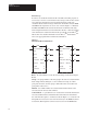
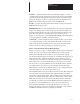
The board calculates the message length before returning a reply to the
PLC Controller.
Depending on the action requested by the block transfer function, the
message length contained in this byte may or may not be the same when
returned from the Node Adapter Board.
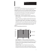
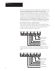
Table 3.A
Block Transfer Message Word 3 – Code Definitions
Class Element (HEX) Word 3 (Decimal)
01 EE Memory Request 01 Recall 257
02 Store 513
03 Initialize 769
02 Read Request 02 Variable/Parameter Value 514
03 Variable/Parameter Full (value, min, max dec, text) 770
04 Read System Clock 1026
06 Fault Code with Primary Fault Text 1538
03 Write Request 02 Parameter value 515
04 Write System Clock 1027
06 Reset Drive* 1539
07 Clear Faults 1795
04 Configuration Request 01 Upload Configuration Table (#50–69) 260
02 Upload Configuration Table (#150–169) 516
03 Upload Configuration Table (#250–269) 772
04 Upload Configuration Table (#350–369) 1028
05 Upload Configuration Table (#450–469) 1284
06 Download Configuration Table (#50–69) 1540
07 Download Configuration Table (#150–169) 1796
08 Download Configuration Table (#250–269) 2052
09 Download Configuration Table (#350–369) 2308
0A Download Configuration Table (#450–469) 2564
0E Trend Upload 01 Read Trend File 270
* No return response for BT
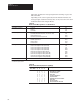
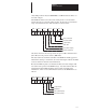
Table 3.B
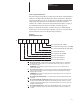
Block Transfer Status Byte (Word 4, High Byte)
Decimal 11 10 9 8
PLC / Octal 13 12 11 10
0 0 0 0 SUCCESSFUL
0 0 0 1 MESSAGE I.D. ERROR
0 0 1 0 ILLEGAL REQUEST
0 0 1 1 NOT USED
0 1 0 0 ILLEGAL PARAMETER
0 1 0 1 ROUTE ERROR
0 1 1 0 IGNORED BECAUSE OF MODE
0 1 1 1 NOT USED
1 0 0 0 OUT OF RANGE
1 0 0 1 EXECUTION MALFUNCTION
Description