
Manual

Chapter 2
Introduction and Product Description
2-3
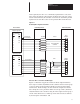
LED Indicators The Node Adapter board contains two LED indicators. The red Processor
Fault LED will illuminate only when a processor malfunction on the Node
Adapter Board has occurred. The green “OK” LED indicates the
communication status between the Node Adapter Board and the PLC
Controller (Refer to Table 2.A).
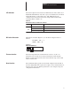
LED State
Table 2.A
LED Indicator Status for Green “OK” indicator
LED Green
LED Off
LED Blinking Green
OK
Function
Normal PLC Communications
No communication to PLC Controller
PLC is in Reset/Program/Test Mode
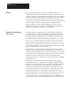
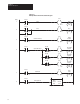
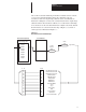
DIP Switch Orientation DIP Switch orientation (Figure 2.3) on the Node Adapter board is as
follows:
CLOSED = “ON” = “1”
OPEN= “OFF” = “0”
Figure 2.3
DIP Switch Orientation
On On Off Off
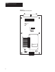
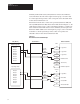
Firmware Location The Node Adapter Board contains firmware version 3.xx (the “xx”
designator may vary but does not effect information in this manual).
Figure 2.4 shows the physical location of the firmware chip on the small
surface mount board.
Board Location The standard mounting position for the Node Adapter board is Port B of
the Drive (Right Hand). If required, the Adapter can be mounted in Port A.
Note that each port uses different parameters to store Adapter setup and
configuration information.