Allen-Bradley Bulletin 1395 Node Adapter Board Catalog No.
Table of Contents Before You Begin Chapter 1 Objective . . . . . . . . . . . . . . . . . . . . . . . . . . . . . . . . . . . . . . . . . . . . . . . Audience . . . . . . . . . . . . . . . . . . . . . . . . . . . . . . . . . . . . . . . . . . . . . . . Vocabulary . . . . . . . . . . . . . . . . . . . . . . . . . . . . . . . . . . . . . . . . . . . . . . Compatibility & Features . . . . . . . . . . . . . . . . . . . . . . . . . . . . . . . . . . Safety Precautions . . . . . . . . . . . . . . . . . . . . . .
Table of Contents Download Configuration Table . . . . . . . . . . . . . . . . . . . . . . . . . . . . . . 3-32 Read Trend Information . . . . . . . . . . . . . . . . . . . . . . . . . . . . . . . . . . . . 3-34 Message Operation . . . . . . . . . . . . . . . . . . . . . . . . . . . . . . . . . . . . . . . 3-35 Installation Chapter 4 Introduction . . . . . . . . . . . . . . . . . . . . . . . . . . . . . . . . . . . . . . . . . . . . . Receiving . . . . . . . . . . . . . . . . . . . . . . . . . . . . . .
Chapter 1 Before You Begin Objective This manual contains the information necessary to perform the following functions on the Bulletin 1395 Node Adapter Board: ❏ Install and Set-up the Node Adapter board ❏ Configure the Drive for control by a PLC Controller ❏ Maintain and Troubleshoot the board Audience This manual is intended for use by expert personnel familiar with the functions of solid state drive equipment.
Chapter 1 Before You Begin Manual Organization Table 1.A provides a brief overview of topics covered in this manual and their location within the book. Table 1.A Manual Organization Specifications Chapter Title 2 Introduction and Product Description Board Identification, Hardware Content, Hardware requirements for Interfacing. 3 Configuration & Interfaces Configuring the Drive for the Node board and interfacing the Drive with a PLC controller.
Chapter 1 Before You Begin General Precautions In addition to the precautions listed throughout this manual, the following statements which are general to the system must be read and understood. ATTENTION: This drive may contain ESD (Electrostatic Discharge) sensitive parts and assemblies. Static control precautions are required when installing, testing, servicing or repairing this assembly. Component damage may result if ESD control procedures are not followed.
Chapter 1 Before You Begin This Page Intentionally Left Blank.
2 Chapter Introduction and Product Description Chapter Objective This chapter contains a description of the major hardware components of the Node Adapter board. It is not intended to be an all encompassing technical description of each hardware component. This chapter provides information to aid service personnel in: ❏ Identifing the Node Adapter board. ❏ Understanding the hardware content of the board.
Chapter 2 Introduction and Product Description Board Configuration The Node Adapter Board causes the Bulletin 1395 Drive to appear as a remote I/O rack to the PLC Controller. Data transfer between the PLC Controller and Drive (at the PLC level) is the same as if the PLC Controller were transferring data to a remote I/O rack. The rack structure consists of two specific types : full or half rack. A full rack is defined as an 8 group rack, while a half rack is defined as a 4 group rack.
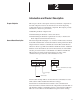
Chapter 2 Introduction and Product Description LED Indicators The Node Adapter board contains two LED indicators. The red Processor Fault LED will illuminate only when a processor malfunction on the Node Adapter Board has occurred. The green “OK” LED indicates the communication status between the Node Adapter Board and the PLC Controller (Refer to Table 2.A). Table 2.
Chapter 2 Introduction and Product Description Figure 2.4 Node Adapter Board Components J1 Processor Fault OK U3 U4 U5 1 8 W1989 V3.
Chapter 3 Functional Description Introduction Chapter 3 contains a general description of the functionality of the Bulletin 1395 Node Adapter Board. This description is intended to provide sufficient background information to support other procedures in this manual and enable the reader to: S Configure the Drive for use with the Node Adapter Board. S Interface the Drive with a PLC Controller. This chapter is not intended to be an all encompassing technical description of the Node Adapter Board.
Chapter 3 Functional Description General The Node Adapter Board does not scale or manipulate data that is transferred between the drive and PLC Controller. As a result, there are no scaling parameters associated with the Node Adapter in the drive. If data in the PLC Controller is manipulated in units other than drive units, the data must first be converted to drive units before being sent to the drive. All scaling of data must be performed in the PLC Controller program.
Chapter 3 Functional Description Data required by the drive on a continuously updated basis is sent (to the drive) using the method of data transfer described above. The rate of data transfer is determined by the standard conventions for determining the I/O update interval of the I/O scanner for the particular PLC Controller used. Figure 3.
Chapter 3 Functional Description Similarly, the External Velocity Ref (Parameter 154) has been linked to source Parameter 301. The 16 bit output word for group 2 of rack 2 must be a 16 bit signed integer whose value corresponds to the allowable values in drive units for Parameter 154. Information from the drive consists of Logic Status (Parameter 100) and Velocity Fdbk (Parameter 106). Based on the links shown in Figure 3.
Chapter 3 Functional Description If the data transferred between the drive and PLC Controller will be manipulated (in the PLC Controller) in units other than drive units, the PLC Controller program must scale the information. The scaled information must be based on the drive units definitions for the parameters in the drive. The External Vel Ref (Parameter 154) is in drive units where 4096 is defined as base speed.
Chapter 3 Functional Description Figure 3.
Chapter 3 Functional Description Due to the fact that bit numbering in the PLC Controller is done in Octal, as opposed to decimal numbering in the drive Parameter 150, it is necessary to relate the output image table bits to the controlled bits in Parameter 150. Figure 3.4 shows the correlation between the output image table bits and the drive Parameter 150 bits.
Chapter 3 Functional Description The first 3 bits of the Logic Command word (Parameter 150 in this example), are used to determine which speed reference will be used by the drive. If the normal run speed reference input to Parameter 154 is to be used, all three bits must be 0. If a preset speed or the MOP function will be used, bits 0–2 are set accordingly (refer to the Bulletin 1395 Installation and Maintenance manual for a complete description of the Logic Command bits).
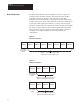
Chapter 3 Functional Description Message Structure Figure 3.5 illustrates the Data File message structure required by the block transfer (BTW ) function in the PLC Controller. The BTR Data File Message does not have to be set up. It will reflect back data depending on the BTW function. The message is segmented into 16 bit words. The first four words (header) must be present. The data portion of the message is only required if the function being executed requires data.
Chapter 3 Functional Description The board calculates the message length before returning a reply to the PLC Controller. Depending on the action requested by the block transfer function, the message length contained in this byte may or may not be the same when returned from the Node Adapter Board. Table 3.
Chapter 3 Functional Description Node Adapter Status Byte The Node Adapter Status Byte is returned from the Node Adapter Board in addition to the Block Transfer Status Byte (Word 4, high byte). The Node Adapter Status Byte appears as the upper byte in the PLC Controller input image table of the first slot associated with the rack. This status byte indicates the condition of the Node Adapter Board itself and is not part of the standard block transfer blocks in the PLC Controller program. Figure 3.
Chapter 3 Functional Description Data Storage In order to use the block transfer blocks in the PLC Controller program, it is necessary to reserve several words for data storage. Some of these words are required for internal use by the block transfer function and some contain the block transfer message information. In the PLC 5TM, the BTW and BTR blocks require the use of two sets of words. Figure 3.
Chapter 3 Functional Description Data File – is the block transfer message illustrated in Figure 3.5 which contains both the header and the data portions of the message. The number of words required for the data file is dependent on the size of the message being sent. In Figure 3.7, N111:5 is the first word in the data file for the BTW block and N111:50 is the first word for the BTR block. Length – specifies the length of the block transfer message in words. The BTR must always be set to 40.
Chapter 3 Functional Description Three bits must be off to allow the execution of the BTW. The first, I : 10 / 11 is set when a block transfer Write to the Node Adapter board is in progress. The second (I : 010 / 12) is the Read available bit. The last is the block transfer wait (I : 010 / 13) bit. This bit indicates that a message has been sent to the drive and is awaiting a response. Two branches are included for error handling.
Chapter 3 Functional Description Figure 3.
Chapter 3 Functional Description Figure 3.
Chapter 3 Functional Description Only ONE parameter may be WRITTEN to or READ from the Drive via the Node Adapter. The BTW block has reserved 6 words starting at N111:5 for the block transfer message. To perform a Write request, the message words must be setup as shown below. Note: The data below is shown in hex.
Chapter 3 Functional Description The message returned from the Node Adapter in this example is basically the same as the header portion of the message sent from the PLC Controller using the BTW block, except that the message length in Word 4 is different. The Class and Element in Word 3 are returned to the PLC Controller as they were received in the Node Adapter. If a block transfer error had occurred, then the ER bit in the BTR block would be set.
Chapter 3 Functional Description Message Formats EE Memory Recall This section of the manual provides a detailed explanation of the messages that the Drive supports. These messages are used by the RIO block transfer interface to program Drive parameters, read parameter data, and control other Drive functions. This function takes the information stored in the Drive’s EEPROM memory and places it in Drive memory.
Chapter 3 Functional Description EE Memory Store This function takes the information in the Drive’s memory and places it in the EEPROM. Any data in the EEPROM prior to issuing the EEPROM STORE command will be erased.
Chapter 3 Functional Description EE Memory Initialize This function initializes the Drive’s memory and EEPROM to a set of default values stored internally in the Drive. IMPORTANT: Any data in Drive memory and EEPROM prior to issuing the EEPROM INITIALIZE command will be erased.
Chapter 3 Functional Description Read Parameter Data This function reads a parameter value from the Drive based on a parameter number provided by the PLC Program.
Chapter 3 Functional Description Read Parameter Full (Value, Min, Max, Descriptor, Text) This function reads the full parameter description from the Drive based on a parameter number provided by the PLC Program. The description includes the actual value, minimum value, maximum value, descriptor, and the parameter text.
Chapter 3 Functional Description Data Format: Parameter Value – Drive units, may need to be scaled by the Controller prior to being used in the Program. Maximum Value – Drive units, may need to be scaled by the PLC Controller prior to being used in the Program. Minimum Value – Drive units, may need to be scaled by the PLC Controller prior to being used in the Program. Descriptor – A numeric value used by Allen-Bradley program terminals to scale parameter data into the appropriate engineering units.
Chapter 3 Functional Description Write Parameter Data This function writes a parameter value to the Drive. The Drive can accept only one parameter at a time when using the RIO write mechanism.
Chapter 3 Functional Description Read System Clock This function reads the system time from the Drive.
Chapter 3 Functional Description Write System Clock This function writes the system time from the PLC Controller to the Drive.
Chapter 3 Functional Description Drive System Reset This function causes the Drive to do a “warm boot restart”. Any data in Drive memory at the time the command is issued is erased and is not saved in EEPROM.
Chapter 3 Functional Description Clear Faults This function requests the Drive to clear any soft or warning faults that have occurred. It also clears the fault buffer. Hard faults cannot be cleared using the command.
Chapter 3 Functional Description Upload Configuration Table This function uploads the configuration table information from the Drive in blocks. Each block of configuration data has a separate function code.
Chapter 3 Functional Description The “x” designator is a position holder. It could represent parameter 150, 250, 350, etc. depending on which configuration table is being requested. NOTE: Word 4 of the BTR instruction is broken down into two bytes. The High byte contains the status bits per Table 3.B. The low byte contains the Drive message length in bytes.
Chapter 3 Functional Description Download Configuration Table This function downloads the configuration table information from the Drive in blocks. Each block of configuration data has a separate function code.
Chapter 3 Functional Description The “x” designator is a position holder. It could represent parameter 150, 250, 350, etc. depending on which configuration table is being sent. WORD BTR 1 0 NOTE: 2 0 3 See Table 4 8 Word 4 of the BTR instruction is broken down into two bytes. The High byte contains the status bits per Table 3.B. The low byte contains the Drive message length in bytes.
Chapter 3 Functional Description Read Trend Information This function reads the trend information from the Drive. The Trend information is broken down into three separate blocks of data. Each block uses the same function code with the message specifing which block is to be read.
Chapter 3 Functional Description Message Operation The READ TREND FILE function is used by a PLC Controller to get information about the Drives trend buffers. This data includes both the setup information and the data samples for each buffer. The BTW message contents determine what data will be returned by the Drive. The following information shows what data will be returned by the Drive (in the BTR instruction) for the Block number specified.
Chapter 3 Functional Description Hour (0 – 23) – An integer value representing the hour the trigger condition was detected. Second (0 – 59) – An integer value representing the second the trigger condition was detected. Millisecond – An integer value representing the 10’s of milliseconds in which the trigger condition was detected. Monitored Parameter Descriptor – An integer value used by Allen-Bradley program terminals to display the proper units for the monitored parameter.
Chapter 3 Functional Description Block #3: This Block contains data samples 67 through 99 for the trend buffer specified in the BTW instruction. BTR Instruction Length: 38 words BTR 0 0 Data Samples – The data samples are specified in Drive Units and may need to be scaled by the PLC Controller prior to being used in the Program.
Chapter 3 Functional Description This Page Intentionally Left Blank.
Chapter 4 Installation Introduction This chapter is a detailed step-by-step procedure for the proper installation of the Bulletin 1395 Node Adapter Board. It also contains electrical and environmental specifications. Procedures performed in this chapter include: S Verification of proper unpacking and inspection S Verification of proper mounting S Verification of proper wiring Receiving It is your responsibility to thoroughly inspect the equipment before accepting shipment from the freight company.
Chapter 4 Installation After determining which port the Node Adapter Board will be connected to, mount the board, using the five (5) panel screws and one (1) phillips head screw supplied (Figure 4.1). Figure 4.1 Configuration Overview J1 J1 * * * * J3 J2 AB0733A Connections The 60 pin ribbon cable connector (J1) located on the Node Adapter Board (see Figure 4.1) provides a means of connecting the board to the Bulletin 1395 Main Control Board port connector (J6 or J7).
Chapter 4 Installation 2. 3. Connect the PLC Controller communication cable to the drive as required by the application.
Chapter 4 Installation Figure 4.2 J2 Connections Blue 1 From Previous Rack (or PLC Controller) Shield 2 Clear 3 Blue 1 To Next Rack Shield 2 Clear 3 Figure 4.
Chapter 4 Installation Switch Settings The Node Adapter Board contains 2 DIP switches, U5 and U6 which perform several different setup functions. The first six positions of switch U5 determine the rack number (in octal) used by the PLC Controller corresponding to the drive. Any of the rack numbers listed in Table 4.A may be used. Each rack number may only be used once, therefore, in applications where several drives are connected to the same communications network (Figure 4.
Chapter 4 Installation Table 4.
Chapter 4 Installation Table 4.
Chapter 4 Installation This Page Intentionally Left Blank.
Chapter 5 Start-Up Introduction This chapter will provide basic procedures that are necessary to configure the drive control for Node Adapter Board use. Procedures that will be covered in this chapter include: S Verification of proper installation and wiring. S Verification of correct switch settings for the required application. S Configuration of the drive control for use with a Node Adapter board. Terminology Configuration – The process of linking Sink to Source parameters.
Chapter 5 Start-Up Example Connection Configuration The parameters used to configure the Node Adapter board are determined by which port of the Bulletin 1395 the Node Adapter is connected to. Figure 5.1 shows a sample configuration with the Node Adapter connected to Port A. Figure 5.2 shows an example of Port B configuration. A detailed functional description of drive configuration is contained in Chapter 3 of this manual.
Chapter 5 Start-Up Figure 5.2 Configuration Example for Node Adapter Connected to Port B of Bulletin 1395 PLC Controller Node Adapter Board Output Image Table Rack No.__ O:0 O:0 O:0 O:0 O:0 O:0 O:0 O:0 0 1 2 3 4 5 6 7 Not Used Input Parameter 1 Input Parameter 2 Input Parameter 3 Input Parameter 4 Input Parameter 5 Input Parameter 6 Input Parameter 7 300 301 302 303 304 305 306 Input Image Table Rack No.
Chapter 5 Start-Up This Page Intentionally Left Blank.
Chapter 6 Troubleshooting and Maintenance Introduction This section describes the Node Adapter board fault diagnostics and how they are processed by the 1395 Drive. All Adapter Boards provide initial fault handling based on conditions within their environment, and then signal the Bulletin 1395 which provides further disposition based on system requirements. Faults are divided into three categories: Hard Faults Hard Faults are non-recoverable.
Chapter 6 Troubleshooting and Maintenance Certain fault conditions in the Bulletin 1395 can be configured in terms of their Soft or Warning Fault nature. That is, the user/operator may specify the action taken, either Soft Fault or Warning Fault (Report Only). ATTENTION: Ignoring faults that have been configured as Report Only could damage certain components in the drive.
Chapter 6 Troubleshooting and Maintenance S NA-14 – BLOCK TRANSFER TYPE Communication malfunction between Node Adapter Board and PLC Controller. Check wiring, PLC Controller, replace Adapter Board. S NA-15 – BLOCK TRANSFER LENGTH Communication malfunction between Node Adapter Board and PLC Controller. Check wiring, PLC Controller, replace Adapter Board. S NA-16 – NO COMM RECEIVED Communication malfunction between Node Adapter Board and PLC Controller. Check wiring, PLC Controller, replace Adapter Board.
Chapter 6 Troubleshooting and Maintenance This Page Intentionally Left Blank.
Chapter 7 Periodic Maintenance Preventive Maintenance ATTENTION: Servicing energized industrial control equipment can be hazardous. Severe injury or death can result from electrical shock, burn, or unintended actuation of controlled equipment. Recommended practice is to disconnect and lock out control equipment from power sources, and allow stored energy in capacitors to dissipate, if present.
Chapter 7 Periodic Maintenance ATTENTION: Use of other than factory recommended test equipment for solid state controls may result in damage to the control or test equipment or unintended actuation of the controlled equipment. Static Sensitive Items – While performing maintenance on the 1395 Drive and the Node Adapter Board, special precautions must be observed in handling or touching certain static sensitive components in the cabinet.
Publication 1395-5.9 ⎯ October, 1995 (Supercedes February, 1995) P/N 133449 Copyright 1995, AllenĆBradley Company, Inc.