
Hardware/Software

Chapter 4
Installation
4–10
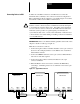
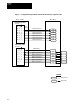
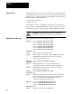
Connecting Devices to DH+ To make the series DH+ connection to the MCA board, connect the
Twinaxial cable (1770–CD) to the connector for the Port configured for
DH+ communications. Refer to Figure 4–4 for details. Figure 4–4 assumes
that channel A will be used for DH+ communications.
!
WARNING: When breaking connections at Channel A on any MCA
Board in a series connected system, communications will be interrupted
to boards that are down line in the series. Depending on the application,
a loss of control to devices connected to these MCA boards could cause
hazardous system operation. To guard against personal injury, the
system must be shut down, or local control maintained of critical devices
connected in the series when making or breaking connections at Channel
A on any MCA Board.
IMPORTANT: Refer to the Twinaxial Cable guidelines at the back of this
chapter for details on cable type, length, etc.
These connections should be made as follows:
1. Connect the signal conductor with blue insulation to the 3-pin connector
(Port A for this example) terminal 2 on the MCA board of each Drive
and the PLC Controller.
2. Connect the SHIELD drain wire to the 3-pin connector SH terminal at
both ends of each cable segment.
3. Connect the signal conductor with clear insulation to the 3- pin
connector terminal 1.
4. When the MCA board is an end device, terminate the DH+ link by
connecting a terminating resistor across terminals 1 and 2 of the 3-pin
connector.
Figure
4-4. T
ypical Daisy Chain DH+ Connection
1
MCA Board
234 1SH 2 1SH2 1
MCA Board
2 3 4 1 SH 2 1 SH 2
J5
CH A CH B J5 CH A CH B
1
MCA Board
234 1SH2 1SH2
J5 CH A CH B
Clear
Shield
Blue