
Hardware/Software

Chapter 4
Installation
4–3
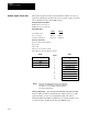
Position
1
– 2
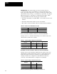
Table
4-A. Discrete Input V
oltage Select, Jumper J4
2
– 3
Input Type
115V AC Input
24V DC Input
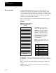
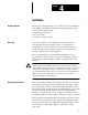
Connection to Allen-Bradley DH+ and/or RIO networks is accomplished
through two connectors located on the bottom of the MCA board (Refer to
Figure 4–1). The first step is to determine what protocol will be used for
each channel. The next two sections explain how to connect RIO and DH+
networks to the Drive.
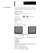
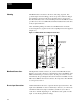
Figure
4-2. T
ypical Discrete Input Connection
MCA
Board
1
15V AC
or
24V DC
1
2
3
4
Input
Return
Gnd
Important: Jumper J4 selects input
voltage level
J5
J4
To Drive TE
Discrete
Device
N.C.
J4
12 3
24V DC
J4
12 3
115V AC
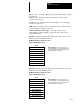
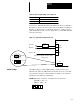
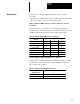
Switch Settings The MCA Adapter contains 4 DIP switches which perform several
different setup functions. DIP switches U5 and U6 are used to select link
type, baud rate, and rack or station number for channel A. U14 and U15
perform the same function for channel B.
NOTE:DIP Switch orientation on the MCA board is as follows:
CLOSED = “ON” = “1”
OPEN = “OFF” = “0”
ON ON Off Off