
Hardware/Software


Chapter 3
Configuration & Interfacing
3–22
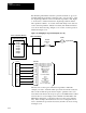
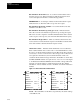
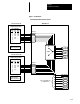
Message Structure Figure 3–16 illustrates the message structure required by the block transfer
(BTW or BTR) function in the PLC Controller. The message is segmented
into 16 bit words. The first four words, commonly called the message
header, must be present. The data portion of the message is only required
for those functions that contain or require data. The following paragraphs
provide a description of each word:
Figure
3-16. Block transfer message header structure
0
0
Element
Status
High Byte Low Byte
0
0
Class
Length
Data
Data
Data
•
•
Word 1
Word 2
Word 3
Word 4
Word 5
Word 6
Word 7
•
•
Message
Header
Data (Optional)
Words 1 and 2 – Used for internal PLC Controller communications
functions. Words 1 and 2 are transparent to the block transfer function and
are always zero.
Word 3 – Contains a code number which determines the function to be
performed by the MCA board upon receipt of the message from the PLC
Controller. Table 3–K summarizes the valid codes which may be used in
word 3. This word is set by the PLC Controller before the message is sent
using the block transfer function. This word is not changed by the Adapter,
therefore, it returns the same data when replying to the PLC Controller.