
Hardware/Software

Chapter 3
Configuration & Interfacing
3–18
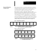
Figure
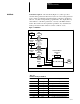
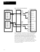
3-13. Discrete PLC Controller I/O Example
Output Image Table
PLC (Rack 2)
PORT B INTERFACE
BULLETIN 1395 DRIVE
307
150
Group
0
Group 1
Group 2
Group 3
Group 4
Group 5
Grpup 6
Group 7
Sinks
Logic Cmd 1
Port B
Sources
151
Logic
Cmd 2
152
Logic Cmd 3
154
External Vel Ref
308
156
157
Sources
Group 0
Group 1
Group 2
Group 3
Group 4
Group 5
Grpup 6
Group 7
Input Image Table
100
Logic
Status
101
Drive Status
357
358
106
112
V
elocity Fdbk
Arm Current Fdbk
Port B
Sinks
DC
T
ach Ref
External T
orque Ref
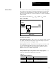
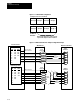
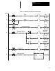
Figure 3–14 provides an example PLC Controller program which could be
used to control the Drive. Based on the configuration shown in Figure
3–13 the PLC Controller program will be transferring information to
parameter 150 and 154 in the Drive. Integer file N7 in the PLC is being
used for Drive logic control and integer file N10 word 01 is used to store
the Drive speed reference. To control the logic operation of the Drive, the
PLC program must control the bits in the output image table which
correspond to the desired operation. Because parameter 300 has been
linked to parameter 150 (Figure 3–2), and parameter 300 is associated with
group 1 in the output image table, the PLC Controller program will be
controlling bits in word 0:21.