
Hardware/Software

Chapter 3
Configuration & Interfacing
3–16
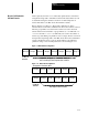
Figure
3-1
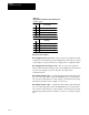
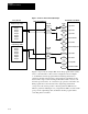
1. RIO Half Rack Configuration
Group
0
Group 1 Group 2 Group 3
Group 4
Each group appears to have a 16 bit
input and output module installed.
Group 5 Group 6 Group 7
Reserved
for Block
Transfer
Configured as 1/2 Lower Rack
Configured as 1/2 Upper Rack
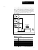
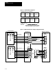
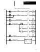
Figure
3-12. Multi Communications Adapter Configuration Example
Output Image Table
PLC Controller
MCA Board
Bulletin 1395 Drive
307
1
2
3
4
Port
B
Channel B
308
309
310
311
312
313
5
6
7
Input
Variables
User
Configurable
Soft Links
DC
ST
ATUS
Reserved for
Block Transfer
357
358
1
2
3
4
5
6
7
Output
Variables
359
360
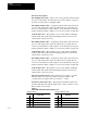
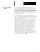
Group Number
Full
0
1
2
3
4
5
6
7
3/4
0/2
1/3
2/4
3/5
4/6
5/7
Half
0/4
1/5
2/6
3/7
Group Number
Full
0
1
2
3
4
5
6
7
3/4
0/2
1/3
2/4
3/5
4/6
5/7
Half
0/4
1/5
2/6
3/7
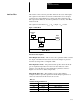
Input Image Table
358
359
360
Block
T
ransfer
Full
Rack
3/4
Rack
Half
Rack
User
Configurable
Soft
Links
Port B
Channel B