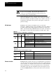
Allen Bradley Bulletin 1395 Multi Communication Board Catalog No.
Table of Contents Before You Begin . . . . . . . . . . . . . . . . . . . . . . . . . . . . . . . . 1-2 Objective . . . . . . . . . . . . . . . . . . . . . . . . . . . . . . . . . . . . . . . . . . Audience . . . . . . . . . . . . . . . . . . . . . . . . . . . . . . . . . . . . . . . . . . Vocabulary . . . . . . . . . . . . . . . . . . . . . . . . . . . . . . . . . . . . . . . . Multi Communications Adapter . . . . . . . . . . . . . . . . . . . . . . . . . . Compatibility & Features . . . . . . . . . . .
ii Table of Contents DH+ Communications . . . . . . . . . . . . . . . . . . . . . . . . . . . . . . . . . DH+ Command Set . . . . . . . . . . . . . . . . . . . . . . . . . . . . . . . . . . Token Pass With Data . . . . . . . . . . . . . . . . . . . . . . . . . . . . . . . . Message Formats . . . . . . . . . . . . . . . . . . . . . . . . . . . . . . . . . . . EE Memory Recall . . . . . . . . . . . . . . . . . . . . . . . . . . . . . . . . . . . EE Memory Store . . . . . . . . . . . . . . . . . . . . . . .
Table of Contents iii Troubleshooting . . . . . . . . . . . . . . . . . . . . . . . . . . . . . . . . 6-1 Chapter Objectives . . . . . . . . . . . . . . . . . . . . . . . . . . . . . . . . . . . Hard Faults . . . . . . . . . . . . . . . . . . . . . . . . . . . . . . . . . . . . . . . . Soft Faults . . . . . . . . . . . . . . . . . . . . . . . . . . . . . . . . . . . . . . . . Warning Faults . . . . . . . . . . . . . . . . . . . . . . . . . . . . . . . . . . . . . MCA Board Fault Messages . . . . . . . .
Chapter 1 Before You Begin Objective This manual contains the information necessary to perform the following functions on the Multi-Communications Adapter (MCA) Board: S Install and Set-up the MCA board S Configure the Drive for control by a PLC Controller S Maintain and Troubleshoot the board Audience This manual is intended for use by expert personnel familiar with the functions of solid state drive equipment.
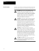
Chapter 1 Before You Begin Safety Precautions The following types of precautionary statements will be found in this manual. IMPORTANT: Identifies particular areas of concern for correct board, processor or drive operation. ATTENTION: Tells you where machinery may be damaged or economic loss can occur if procedures are not followed properly. Or it tells you where people may be hurt if procedures are not followed properly.
Chapter 1 Before You Begin General Precautions In addition to the precautions listed throughout this manual, the following statements which are general to the system must be read and understood. ! ! ! ! 1–4 CAUTION: This drive may contain ESD (Electrostatic Discharge) sensitive parts and assemblies. Static control precautions are required when installing, testing, servicing or repairing this assembly. Component damage may result if ESD control procedures are not followed.
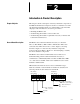
Chapter 2 Introduction & Product Description Chapter Objective This chapter contains a description of the major hardware components of the Multi-Communications Adapter board. It is not intended to be an all encompassing technical description of each hardware component. This chapter provides information to aid service personnel in: S Identifing the MCA board. S Understanding the hardware content of the board.
Chapter 2 Introduction and Product Description ATTENTION: Certain procedures in this manual require that the drive “Not be running”. This assumes that the DC loop contactor is de-energized and that the user has properly set up the interface logic to meet this criteria. ! Additional hardware allows for a separate discrete input to the Drive. The input device (Pushbutton, selector switch, etc) is connected to terminal block J5 and is jumper selectable (see table 2–A) for either a 115V AC or 24V DC input.
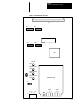
Chapter 2 Introduction and Product Description Figure 2-1.
Chapter 2 Introduction and Product Description DIP Switch Orientation DIP Switch orientation (Figure 2–2) on the MCA board is as Follows: CLOSED = “ON” = “1” OPEN= “OFF” = “0” Figure 2-2. DIP Switch Orientation On On Off Off Board Location The standard mounting position for the MCA board is Port B of the Drive (Refer to Figure 2–3). If required, the Adapter can be mounted in Port A. Note that each port uses different parameters to store Adapter setup and configuration information. Figure 2-3.
Chapter 3 Configuration & PLC Interfacing Chapter Objective This chapter contains a general description of the MCA Board’s features and functions. It is intended to provide background information to support other procedures in this manual and help you to: S Configure the Drive for use with the MCA Board S Interface the Drive with an Allen-Bradley PLC Controller. This chapter is not intended to be an all encompassing technical description of the MCA Board.
Chapter 3 Configuration & Interfacing Parameter Table – A table which contains all parameters that are available in the Drive and adapters. Source Parameter – A parameter that contains real time information that is available for use by other devices. These devices can include PLC controllers, operator interface devices, program terminals, etc. Sink Parameter – Sink parameters accept data from other parameters which is then used by the Drive to perform the desired functions.
Chapter 3 Configuration & Interfacing Figure 3-1.
Chapter 3 Configuration & Interfacing Discrete Input The MCA board has a single discrete input which can be programmed for use in the Drive. Figure 3–2 shows this input and the parameters that control its use. Figure 3-2. Discrete Input Bit # Specifier Parameter 519 518 J5 Stop J4 1 2 3 0 1 2 • • • 15 115VAC/24VDC Select 4 300 301 • • • 314 J4 ! Position Input 1–2 2–3 24VDC 115VAC 520 Operator ATTENTION: The Start/Stop circuitry in this drive is composed of solid-state components.
Chapter 3 Configuration & Interfacing Discrete Input Bit Specifier (Par #519) – This parameter determines which bit of the parameter specified by the Discrete Input Map will be affected by the discrete input. Jumper J4, 115V AC/24V DC select – This jumper allows the selection of the input voltage required to operate the discrete input. Refer to Table 3–B. Discrete Input Operator (Par # 520) – Determines how the discrete input will affect the bit specified by the Discrete Input Bit Specifier.
Chapter 3 Configuration & Interfacing Figure 3-3. Constant Parameter Example MCA Board Input 504 550 Constant #1 550 1000 Multiply #1 Block By placing the constant #1 parameter number (Par #550) into the input parameter (Par #504) the data value of 1000 in constant parameter (P #550) is used as the input to the Multiply 1 block.
Chapter 3 Configuration & Interfacing Multiply Block #1 General Description – This block (Fig. 3–5) receives an input (parameter 504) and multiplies it by a gain value (parameter 505). The output can be linked to other Drive parameters or used by the MCA board with other function blocks. The overflow control parameter (parameter 517) determines the fault type and action taken when an overflow condition occurs. Figure 3-5.
Chapter 3 Configuration & Interfacing Overflow Control (Par # 517) – This parameter determines what action the Drive will take when a Block Output value overflow condition occurs. Refer to Table 3–E for details. Table 3-E.
Chapter 3 Configuration & Interfacing Multiply Block #2 General Description – This block (Figure 3–6) receives two inputs (parameter 506 & 507) and multiplies them together. The output is available as two parameters, whole and fractional values (providing 32 bit resolution), and can be linked to other Drive parameters or used by the other MCA function blocks. The overflow control parameter (Par 517) determines the fault type and action taken when an overflow condition occurs. Figure 3-6.
Chapter 3 Configuration & Interfacing Table 3-G. Function Block Overflow Control, Parameter 517 Overflow Action BIT 3 12 0 0 1 1 0 1 0 1 Action Taken Send last state (Default) Zero Inputs Send max value, pos or neg None Overflow fault Severity BIT 5 4 0 0 1 1 0 1 0 1 Fault Type None (Default) Warning Soft Hard Parameter Description: Block Output Whole (Par # 316) – This is a fast source parameter which contains the whole number part of the multiplication.
Chapter 3 Configuration & Interfacing Add Block General Description – The Add block (Figure 3–7) sums up to three external values (parameters 508, 510, 512) and one offset value (parameter 514) to obtain a result. Each external input has a scale factor (parameters 509, 511, 513) that is independently programmable. The output (Par 318) can be linked to other Drive parameters or used by other MCA function blocks.
Chapter 3 Configuration & Interfacing Parameter Description: Block Output (Par # 318) – This is a fast source parameter which contains the result of the addition. The data can be used on the Adapter or passed to the Drive by using a Drive configuration link. Block Input #1 (Par # 508) – A parameter that specifies where this block gets one of the input values used in the addition process. Input data can come from other functions on this Adapter or from the Drive by using CA Indirect parameters.
Chapter 3 Configuration & Interfacing Low Pass Filter This block is a first order low pass filter which can be used to filter inputs. The equation for this filter is shown below. This block receives an input (parameter 515) and multiplies it by a filter gain value (parameter 516). The output can be linked to other Drive parameters or used by other MCA function blocks. The equation for this filter is: Ynew= Yold + (Input – Yold) * Gain. Figure 3-8.
Chapter 3 Configuration & Interfacing RIO Communications Each channel of the MCA board can be configured for Allen-Bradley Remote I/O (RIO) communications. Configuration as a RIO device allows the Drive to look like a remote I/O chassis to a PLC. The MCA board has several features, some of which are not available with the Node Adapter board. This adapter can replace the Node Adapter board in applications where these additional communications features are required.
Chapter 3 Configuration & Interfacing Discrete PLC Controller I/O Data Transfer Data required by the Drive on a continuously updated basis is transferred using the I/O image table of the PLC Controller. The data transfer rate can be determined using the standard conventions for I/O rack updates of discrete I/O. Refer to the PLC Controller manual for details. Refer to Figures 3–9 thru 3–11. These figures indicate how data is transferred between the Drive and PLC controller for the rack size selected.
Chapter 3 Configuration & Interfacing Figure 3-11. RIO Half Rack Configuration Configured as 1/2 Lower Rack Group 0 Group 1 Group 2 Group 3 Configured as 1/2 Upper Rack Group 4 Reserved for Block Transfer Group 5 Group 6 Group 7 Each group appears to have a 16 bit input and output module installed. Figure 3-12.
Chapter 3 Configuration & Interfacing Discrete PLC Controller I/O Example Figure 3–13 illustrates an application where the MCA Board has been setup for a full rack (numbered rack 2) and the 16 bit words for group 1 and 2 are being used by the PLC Controller program for data transfer with the Drive. In this example, the Drive has been configured so that the data coming into source parameter 307 is sent to Logic Cmd 1 (parameter 150).
Chapter 3 Configuration & Interfacing Figure 3-13.
Chapter 3 Configuration & Interfacing Figure 3-14.
Chapter 3 Configuration & Interfacing Bit numbering in the PLC Controller is performed in Octal, as opposed to Decimal numbering in the Drive parameter 150, so it is necessary to relate the output image table bits to the controlled bits in parameter 150. Figure 3–15 shows the correlation between the output image table bits and the Drive parameter 150 bits.
Chapter 3 Configuration & Interfacing If the normal run speed reference is selected, the PLC Controller must send a 16 bit word to External Vel Ref (parm 154) in the Drive. Because the speed reference is a complete 16 bit word, the PLC Controller must send the data as a complete word rather than as individual bits as was the case for logic command bits. In this example, word 1 of integer file N10 is used to store the speed reference for the Drive.
Chapter 3 Configuration & Interfacing Message Structure Figure 3–16 illustrates the message structure required by the block transfer (BTW or BTR) function in the PLC Controller. The message is segmented into 16 bit words. The first four words, commonly called the message header, must be present. The data portion of the message is only required for those functions that contain or require data. The following paragraphs provide a description of each word: Figure 3-16.
Chapter 3 Configuration & Interfacing Table 3-K Block Transfer Message Word 3 - Code Definitions Message Type EE Memory Request Read Request Write Request Configuration Request Auto Tune Trend Upload Message Recall Store Initialize Parameter Value Parameter Full (value, min, max dexc, text) Read System Clock Parameter Value Write System Clock Reset Drive Clear Faults Upload Configuration Table (#50 – 69) Upload Configuration Table (#150 – 169) Upload Configuration Table (#250 – 269) Upload Configur
Chapter 3 Configuration & Interfacing Word 4, High byte – This byte contains the block transfer status byte (see Table 3–L) which is a code number returned from the MCA board as a response to the block transfer function. This byte is not used by the PLC Controller when sending data to the Adapter and therefore is set to 0 when performing a block transfer write in the PLC Controller program. Table 3-L.
Chapter 3 Configuration & Interfacing MCA Status Word The status word is returned from the MCA Board to the PLC Controller in addition to the Block Transfer Status Byte (Word 4, high byte). The MCA status word appears as the first slot (or word) in the rack assigned to the Multi-Communications Adapter (Refer to Figure 3–17). This status byte indicates the condition of the MCA itself and is not included as part of the PLC Controller block transfer instruction.
Chapter 3 Configuration & Interfacing Block Transfer Write in Process – Is set when a block transfer write to the Drive is in process. This bit remains set until the message has been received and placed in the Drive’s internal message buffer. IMPORTANT: Do not attempt to initiate another block transfer request while this bit is set. The Drive will not respond to the request. Block Transfer Read Data Available – Is set when the Drive has data available for the PLC to read.
Chapter 3 Configuration & Interfacing Group: – The group number of the first in the group in the rack as specified above. If the Drive is setup as a 3/4 rack, the first group could be 0 or 2. If the Drive has been setup as a full rack, group number is 0. If the Drive is setup as a half rack, the first group number could be 0 or 4. Refer to Figures 3–9 through 3–11 for details. Module: – The module number associated with the block transfer function in the first group. This is always set to 0.
Chapter 3 Configuration & Interfacing RIO Redundant Mode The RIO redundant mode is a special mode that allows the Drive to be connected to the RIO channel of two separate PLC Controllers. A parameter in the Drive specifies which PLC Controller has control of the Drive. Output image table data from the non-controlling PLC is discarded. Figure 3–19 shows a typical redundant mode configuration. The redundant RIO mode is only available when the following three conditions are met: 1.
Chapter 3 Configuration & Interfacing Figure 3-19.
Chapter 3 Configuration & Interfacing DH+ Communications Each channel of the MCA board can be configured for Data Highway + (DH+) communications. Configuration as a DH+ device allows the Drive to look like a station on the DH+ link. Below is a listing of the DH+ features on this Adapter: S The Adapter supports 57.6K, 115K, and 230K baud communication rates. S Supports Parameter read and parameter write messages for blocks of parameters.
Chapter 3 Configuration & Interfacing PLC Typed Read (N11:499–999) – This request reads the status of the previous parameter writes (N10:500–999). If a Typed Read is specified with an PLC address of N11:499, the write status of all parameters from the last TYPED WRITE request (N10: xxx–xxx) will be OR’ed together. If one error has occurred during the last write operation, this address will contain the parameter number where the error occurred.
Chapter 3 Configuration & Interfacing Token Pass With Data This is a special mechanism built into the MCA board that allows the Drive to transfer data between stations on a DH+ link along with the link token. Refer to Figure 3–20. The amount of information passed is limited as follows: S Each station (each channel of an MCA board) can add two parameters values to the list of values transferred with the token.
Chapter 3 Configuration & Interfacing Figure 3-20.
Chapter 3 Configuration & Interfacing Figure 3-21. PLC5/15 - 1395 DC Drive Sample Program Rung 2:0 This rung will read parameters 100 – 109 when bit B3/0 is toggled from zero to one. The parameter information is stored in N20: 0 –9 in this PLC. The drive DH+ station ID is 11.
Chapter 3 Configuration & Interfacing Figure 3-21. PLC5/15 - 1395 DC Drive Sample Program cont. Rung 2:1 This rung will read parameters 100 – 109 on a continuous basis by using the Message Block enable bit to toggle the next message The parameter information is stored in N20: 0 –9 in this PLC. The drive DH+ station ID is 11.
Chapter 3 Configuration & Interfacing Figure 3-21. PLC5/15 - 1395 DC Drive Sample Program cont. Rung 2:2 This rung will write to parameters 500 – 999 in the drive when bit B3/1 is toggled from a zero to a one. The parameter values to be sent to the drive are stored in N30: 0 – 499.
Chapter 3 Configuration & Interfacing Message Formats This section of the manual provides a detailed explanation of the messages that the Drive supports. These messages are used by the RIO block transfer interface and the DH+ block transfer emulation to program Drive parameters, read parameter data, and control other Drive functions. EE Memory Recall This function takes the information stored in the Drive’s EEPROM memory and places it in Drive memory.
Chapter 3 Configuration & Interfacing EE Memory Store This function takes the information in the Drive’s memory and places it in the EEPROM. Any data in the EEPROM prior to issuing the EEPROM STORE command will be erased.
Chapter 3 Configuration & Interfacing EE Memory Initialize This function initializes the Drive’s memory and EEPROM to a set of default values stored internally in the Drive. IMPORTANT: Any data in Drive memory and EEPROM prior to issuing the EEPROM INITIALIZE command will be erased.
Chapter 3 Configuration & Interfacing Read Parameter Data This function reads parameter value(s) from the Drive based on a parameter number list provided by the PLC Program. The Drive can supply up to 30 parameters in one block transfer reply when using the RIO Read Parameter. The DH+ message can only read one parameter per request.
Chapter 3 Configuration & Interfacing The BTW length is determined by adding the message header length (4 words) to the number of words required to specify the parameter list. Each parameter requested requires two words in the BTW instruction with the exception of the last parameter in the list. The last parameter requires only one word. Below are two examples: Example 1: The PLC Controller is to read 1 parameter value from the Drive.
Chapter 3 Configuration & Interfacing Read Parameter Full (Value, Min, Max, Descriptor, Text) This function reads the full parameter description from the Drive based on a parameter number provided by the PLC Program. The description includes the actual value, minimum value, maximum value, descriptor, and the parameter text.
Chapter 3 Configuration & Interfacing Data Format: Parameter Value – Drive units, may need to be scaled by the Controller prior to being used in the Program. Maximum Value – Drive units, may need to be scaled by the PLC Controller prior to being used in the Program. Minimum Value – Drive units, may need to be scaled by the PLC Controller prior to being used in the Program. Descriptor – A numeric value used by Allen-Bradley program terminals to scale parameter data into the appropriate engineering units.
Chapter 3 Configuration & Interfacing Write Parameter Data This function writes parameter value(s) to the Drive. The Drive can accept up to 30 parameters in one block transfer write when using the RIO write mechanism. The DH+ message can only write one parameter per message.
Chapter 3 Configuration & Interfacing The BTW length is determined by adding the message header length (4 words) to the number of words required to specify the parameter list and data. Each parameter change requires two words in the BTW instruction. Below are two examples: Example 1: The PLC Controller is to read 1 parameter value from the Drive.
Chapter 3 Configuration & Interfacing Read System Clock This function reads the system time from the Drive.
Chapter 3 Configuration & Interfacing Write System Clock This function writes the system time from the PLC Controller to the Drive.
Chapter 3 Configuration & Interfacing Drive System Reset This function causes the Drive to do a “warm boot restart”. Any data in Drive memory at the time the command is issued is erased and is not saved in EEPROM.
Chapter 3 Configuration & Interfacing Clear Faults This function requests the Drive to clear any soft or warning faults that have occurred. It also clears the fault buffer. Hard faults cannot be cleared using the command.
Chapter 3 Configuration & Interfacing Upload Configuration Table This function uploads the configuration table information from the Drive in blocks. Each block of configuration data has a separate function code.
Chapter 3 Configuration & Interfacing The “x” designator is a position holder. It could represent parameter 150, 250, 350, etc. depending on which configuration table is being requested. BTR NOTE: Word 4 of the BTR instruction is broken down into two bytes. The High byte contains the status bits per Table 3–H. The low byte contains the Drive message length in bytes.
Chapter 3 Configuration & Interfacing Download Configuration Table This function downloads the configuration table information from the Drive in blocks. Each block of configuration data has a separate function code.
Chapter 3 Configuration & Interfacing The “x” designator is a position holder. It could represent parameter 150, 250, 350, etc. depending on which configuration table is being sent. WORD 1 BTR 0 2 0 3 See Table 4 8 NOTE: Word 4 of the BTR instruction is broken down into two bytes. The High byte contains the status bits per Table 3–H. The low byte contains the Drive message length in bytes.
Chapter 3 Configuration & Interfacing Autotune Measure Motor Inertia Puts the Drive in the Autotune Mode for measuring motor inertia. When in this mode the Drive gathers information about motor inertia by accelerating and decelerating the motor under conditions controlled by the Autotune firmware. ATTENTION: When in the Autotune Mode the Drive controls motor operation using a speed profile determined internally. Carefully read the section on auto tuning sequencing prior to using this command.
Chapter 3 Configuration & Interfacing Message Operation – Puts the Drive in the Autotune Mode for measuring motor inertia. Once in this mode the Drive waits for a “START” input to the Drive before beginning the measure procedure. The procedure gathers information about motor inertia by accelerating and decelerating the motor under conditions controlled by the Autotune firmware. Refer to the Drive Instruction manual (1395–5.xx) for a complete description of how Autotuning operates.
Chapter 3 Configuration & Interfacing Autotune Update Motor Inertia This function updates the Drives internal database with the motor inertia (parameter 613) calculated by the autotune firmware and provides the data to the PLC Controller in the BTR message.
Chapter 3 Configuration & Interfacing Autotune Measure System Inertia Puts the Drive in the Autotune Mode for measuring system inertia. When in this mode the Drive determines the total system inertia including the motor and connected load by accelerating and decelerating the motor under conditions controlled by the Autotune firmware. ATTENTION: When in the Autotune Mode the Drive controls motor operation using a speed profile determined internally.
Chapter 3 Configuration & Interfacing Refer to the Drive instruction manual (1395–5.xx) for a complete description of how Auto tuning operates. This function requires the message header only. The status byte will indicate the success or ineffectiveness of the request.
Chapter 3 Configuration & Interfacing Autotune Tune Velocity Loop This function calculates the required velocity loop gains based on the data determined by the motor inertia test, system inertia test, and damping factor (Parameter #702).
Chapter 3 Configuration & Interfacing Autotune Update Velocity Tune This function updates the Drives internal database with the velocity loop parameters calculated by the Tune Velocity Loop function and provides the data to the PLC Controller in the BTR message.
Chapter 3 Configuration & Interfacing Read Trend Information This function reads the trend information from the Drive. The Trend information is broken down into three separate blocks of data. Each block uses the same function code with the message specifing which block is to be read.
Chapter 3 Configuration & Interfacing Message Operation The READ TREND FILE function is used by a PLC Controller to get information about the Drives trend buffers. This data includes both the setup information and the data samples for each buffer. The BTW message contents determine what data will be returned by the Drive. The following information shows what data will be returned by the Drive (in the BTR instruction) for the Block number specified.
Chapter 3 Configuration & Interfacing Day (1 – 31) – An integer value representing the day the trigger condition was detected. Hour (0 – 23) – An integer value representing the hour the trigger condition was detected. Second (0 – 59) – An integer value representing the second the trigger condition was detected. Millisecond – An integer value representing the 10’s of milliseconds in which the trigger condition was detected.
Chapter 3 Configuration & Interfacing Block #3: This Block contains data samples 67 through 99 for the trend buffer specified in the BTW instruction. BTR Instruction Length: 38 words BTR 0 0 270 See Note 3 Data Sample #67 Data Sample #68 • Data Sample #99 3–64 Data Samples – The data samples are specified in Drive Units and may need to be scaled by the PLC Controller prior to being used in the Program.
Chapter 4 Installation Chapter Objective This chapter is a detailed step-by-step procedure for the proper installation of the Bulletin 1395 Multi-Communications Adapter Board. Procedures performed in this chapter include: S Unpacking and inspection S Proper mounting S Connection & Switch Settings Receiving It is your responsibility to thoroughly inspect the equipment before accepting shipment from the freight company. You must take the responsibility for noting any damage.
Chapter 4 Installation Mounting The MCA Board is mounted on the front of the swing out panel. Two possible adapter board mounting positions are provided. When looking at the mounting positions from the front, the right position corresponds to Port B and the left to Port A. The standard port used for the MCA board is port B, however if a second MCA Board will be installed in the same drive, it may be placed in Port A.
Chapter 4 Installation Table 4-A. Discrete Input Voltage Select, Jumper J4 Position Input Type 1–2 24V DC Input 2–3 115V AC Input Connection to Allen-Bradley DH+ and/or RIO networks is accomplished through two connectors located on the bottom of the MCA board (Refer to Figure 4–1). The first step is to determine what protocol will be used for each channel. The next two sections explain how to connect RIO and DH+ networks to the Drive. Figure 4-2.
Chapter 4 Installation IMPORTANT: The switch settings are read by the Drive when it is powered up and/or when a “System Reset” is performed. If changes are made to the switch settings after one of these occurances they will not take effect until the next power-up or “System Reset” is performed. Any illegal DIP switch settings or combinations is annunciated with a fault. When setting up the MCA board the following steps should be taken: 1.
Chapter 4 Installation RIO Installation Connection to an Allen-Bradley RIO network requires two basic procedures: S The MCA board DIP switches must be configured for the desired setup. S The physical wire connections to the board are made. Switch settings for RIO rack size (switch U5 channel A, and U14 channel B): Switch positions 6–8 set the rack size for the MCA board. The size determines how much real time data can be transferred between the Drive and PLC Controller.
Chapter 4 Installation Switch settings for RIO Rack Address (switch U6 channel A, and U15 channel B): Switch positions 3–8 determine the rack address of the MCA adapter. Refer to Table 4–G for details. Table 4-G.
Chapter 4 Installation Connecting Devices to RIO To make the series RIO connection to the MCA board, connect the Twinaxial cable (1770–CD) to the connector for the Port configured for RIO communications. Refer to Figure 4–3 for details. Figure 4–3 assumes that channel A will be used for RIO communications. ! ATTENTION: When breaking connections at Channel A on any MCA Board in a series connected system, communications will be interrupted to boards that are down line in the series.
Chapter 4 Installation DH+ Installation Connection to an Allen-Bradley DH+ network requires two basic procedures to be followed: S The MCA board DIP switches must be configured for the desired setup. S The physical wire connections to the board are made. Switch settings for DH+ Station Address (switch U6 channel A, and U15 channel B): Switch positions 3–8 determine the station address of the MCA adapter. Refer to Table 4–H for details.
Chapter 4 Installation Table 4-H.
Chapter 4 Installation Connecting Devices to DH+ To make the series DH+ connection to the MCA board, connect the Twinaxial cable (1770–CD) to the connector for the Port configured for DH+ communications. Refer to Figure 4–4 for details. Figure 4–4 assumes that channel A will be used for DH+ communications. ! WARNING: When breaking connections at Channel A on any MCA Board in a series connected system, communications will be interrupted to boards that are down line in the series.
Chapter 4 Installation Twinaxial Cable Guidelines Twinaxial cable used for Remote I/O (RIO) and Data Highway + (DH+) communications represents a communications transmission line in which certain characteristics exist. The following are some general guidelines which apply to this particular transmission line and should be adhered to in order to obtain the best possible results.
Chapter 5 Start Up Chapter Objectives This chapter will provide you with the basic procedures that are necessary to configure the Drive for use with a MCA Board. Procedures that will be covered in this chapter include: S Verification of proper installation and wiring. S Verification of correct switch settings for the required application. S Configuration of the Drive control for use with the MCA Board. Terminology Connection Verification Configuration The process of linking Sink to Source parameters.
Chapter 5 Start Up Figure 5-1. Configuration Example, MCA Board in Port B with Channel A designated as RIO PLC Controller MCA Board Output Image Table Rack No. _ O : 0 __0 O : 0 __1 Not Used O : 0 __2 O : 0 __3 O : 0 __4 O : 0 __5 O : 0 __6 O : 0 __7 Input Parameter 1 Input Parameter 2 Input Parameter 3 Input Parameter 4 Input Parameter 5 Input Parameter 6 Input Parameter 7 300 301 302 303 304 305 306 Input Image Table Rack No.
Chapter 6 Troubleshooting Chapter Objectives This section describes the MCA board fault diagnostics and how they are processed by the 1395 Drive. Using the MCA Fault Board messages will help you to isolate problem areas and initiate possible solutions. WARNING: Only qualified personnel familiar with the 1395 Drive system should perform troubleshooting or maintenance functions on the MCA Board. Failure to comply may result in personal injury and/or equipment damage.
Chapter 6 Troubleshooting Warning Faults Warning Faults are the lowest priority and indicate error conditions which are generally transient in nature, but could result in undesirable operation if allowed to persist. If left uncorrected, Warning Faults could result in a Soft Fault. Examples of Warning Faults are: S Function Block Overflow S RIO Comm Loss Selected Fault conditions in the Bulletin 1395 Drive can be configured in terms of their Soft or Warning Fault nature.
Chapter 6 Troubleshooting Action: Check DIP switch settings and reset drive, if condition persists replace adapter board. Message: CA–35–ADD FUNC BLK OVERFLOW Fault Type: Warning/Soft Cause: The Add function block output value has overflowed. Action: Check range on inputs, gains values, and offset values for ADD block. Message: CA–36–MULT1 FUNC BLK OVERFLOW Fault Type: Warning/Soft Cause: The Multiplication function block output value has overflowed. Action: Check input range and gain value.
Chapter 6 Troubleshooting Message: CA–64–ADAPTER PROCESSOR FAULT Fault Type: Hard Cause: Adapter internal diagnostic malfunction. Action: Check dip switch settings and reset drive, if condition persists replace adapter board. RIO Faults Message: CA–70–RESET/PROGRAM/TEST (CHA) CA–85–RESET/PROGRAM/TEST (CHB) Fault Type: Soft/Warning Cause: PLC was switched from run mode to another mode. Action: Check PLC mode switch and I/O control reset, if condition persists, replace adapter board.
Chapter 7 Periodic Maintenance Preventative Maintenance WARNING: Servicing energized industrial equipment can be hazardous. Severe injury or death can result from electrical shock, burn, or unintended actuation of controlled equipment. Recommended practice is to disconnect and lock out control equipment from power sources, and allow stored energy in capacitors to dissipate, if present.
Chapter 7 Periodic Maintenance Periodic Inspection – Industrial control equipment should be inspected periodically. Inspection intervals should be based on environmental and operating conditions, and adjusted as indicated by experience. An initial inspection within 3 to 4 months after installation is suggested.
Chapter 7 Periodic Maintenance Tests & Records Final Check Out – After maintenance or repair of industrial controls, always test the control system for proper functioning under controlled conditions that avoid hazards in the event of a control malfunction. “Keep Good Maintenance Records” – This rule will be most helpful in locating possible intermitttent problems by pointing to a particular area of recurring trouble within the overall system.
Chapter 8 Reference Chapter Objective This chapter provides you with an easy reference to the MCA board parameters. It includes a condensed table of all configuration and setup parameters and a complete description of each MCA board parameter. Terminology A brief description of terms and concepts covered in this chapter are: Channel Refers to a serial communication link. The MCA board contains two “channels”, each of which can be assigned as either Allen–Bradley RIO or DH+ type communications.
Chapter 8 Reference Parameter A memory location in Drive firmware used to store Drive data. This data can be realtime data and/or Drive setup information. Each parameter has an assigned number and function. Parameters are displayed in engineering units when viewed from program terminals. Parameter Table A table which contains all parameters that are available in the Drive. Source Parameter A parameter which contains real time information that is available for use by other devices.
Chapter 8 Reference Table 8-A.
Chapter 8 Reference S S S S S S S S S S S S S S S #309 – #314 #350 – #356 #357 – #363 #364 – #369 #400 – #406 #407 – #413 #450 – #456 #457 – #463 #464 – #469 #500 – #524 #525 – #536 #537 – #549 #550 – #574 #575 – #586 #587 – #599 Comm Adapter Source Parameters Port B Channel A Sinks Port B Channel B Sinks Comm Adapter Indirect Sinks Port A Channel A Source Parameters Port A Channel B Source Parameters Port A Channel A Sinks Port A Channel B Sinks Comm Adapter Indirect Sinks Port B Comm Adapter Setup Para
Chapter 8 Reference Table 8-A.
Chapter 8 Reference Table 8-B.
Chapter 8 Reference Table 8-B. Listing of Parameters that do not change with Channel Assignment (cont.) PORT DEC HEX NAME UNITS INIT B B B B B B B B A A A A A A A A A A A A A A A A A A A A A A A A 516 517 518 519 520 523 524 549 550 204H 205H 206H 207H 208H 20BH 20CH 225H 226H B>LP Filter Time B>FB Ovrflow Sel B>Disc In-Param B>Disc In-Bit B>Disc In-Oper B>ChA Dip Switch B>ChB Dip Switch B>CA: Version No A>CA Constant 1 Sec Bit Select None None None None None None None 0.
Chapter 8 Reference Parameter Descriptions The format used to provide information about MCA board parameters is as follows: Parameter AAA [Parameter name] BBB [Parameter name] Use: Parameter Type: Program Terminal Units: Minimum Value: Maximum Value: Default Value: Description: Parameter AAA – The parameter number if the Adapter is installed in Port A. Parameter BBB – The parameter number if the Adapter is installed in Port B. [Parameter name] – The parameter name as viewed on a program terminal.
Chapter 8 Reference Common Parameters This section describes in detail the function of each of the parameters on the MCA board that remains the same regardless of the boards channel assignments.
Chapter 8 Reference Parameter 417 – [A>Mult2 FB Fract] Parameter 317 – [B>Mult2 FB Fract] Use: Fractional value Output from Multiply #2 function block Parameter Type: Fast Source Program Terminal Units: None Minimum Value: –32767 Maximum Value: 32767 Default Value: None Description: This parameter is a fast source that contains the fractional portion of the output resultant from the Multiply #2 function block.
Chapter 8 Reference Parameter 464 – [A>CA Indirect 1] Parameter 364 – [B>CA Indirect 1] Use: A fast sink parameter for use by the function blocks Parameter Type: Fast Sink Program Terminal Units: None Minimum Value: –32767 Maximum Value: 32767 Default Value: None Description: This parameter is a fast sink used by function blocks to obtain information from Drive parameters whose source is outside of the MCA board. This parameter can be linked to any Drive source parameter.
Chapter 8 Reference Parameter 468 – [A>CA Indirect 5] Parameter 368 – [B>CA Indirect 5] Use: A fast sink parameter for use by the function blocks Parameter Type: Fast Sink Program Terminal Units: None Minimum Value: –32767 Maximum Value: 32767 Default Value: None Description: This parameter is a fast sink used by function blocks to obtain information from Drive parameters whose source is outside of the MCA board. This parameter can be linked to any Drive source parameter.
Chapter 8 Reference Parameter 552 – [A>CA Constant 3] Parameter 502 – [B>CA Constant 3] Use: Stores a constant for use by function blocks Parameter Type: Setup Program Terminal Units: None Minimum Value: –32767 Maximum Value: 32767 Default Value: 0 Description: This parameter can be used to store a constant value for use by the function blocks.
Chapter 8 Reference Parameter 555 – [A>Mult1 FB Gain] Parameter 505 – [B>Mult1 FB Gain] Use: Specifies Multiply #1 gain value Parameter Type: Setup Program Terminal Units: None Minimum Value: –15.999 Maximum Value: 15.995 Default Value: 0 Description: This parameter specifies the Multiply #1 gain value. The gain value is multiplied by the input data to obtain the Multiply #1 output value (Par. #315).
Chapter 8 Reference Parameter 558 – [A>Add FB In 1] Parameter 508 – [B>Add FB In 1] Use: Specifies an input to the Add function block Parameter Type: Setup Program Terminal Units: None Minimum Value: B–300/A–400 Maximum Value: B–503/A–553 Default Value: B–320/A–420 Description: This parameter specifies where the Add function block gets one of its inputs. Input data can come from other functions on this Adapter or from the Drive by using a CA Indirect parameter linked to the desired information.
Chapter 8 Reference Parameter 561 – [A>Add FB Gain 2] Parameter 511 – [B>Add FB Gain 2] Use: Specifies Add input #2 gain value Parameter Type: Setup Program Terminal Units: None Minimum Value: –15.999 Maximum Value: 15.995 Default Value: 0 Description: This parameter specifies the Add input #2 gain value. The gain value is multiplied by the input #2 data prior to the summation of all block values.
Chapter 8 Reference Parameter 564 – [A>Add FB Off 4] Parameter 514 – [B>Add FB Off 4] Use: A constant value used as an input in the Add function block Parameter Type: Setup Program Terminal Units: None Minimum Value: –32767 Maximum Value: 32768 Default Value: 0 Description: This parameter contains a value that is added to the other three Add function block inputs. It may be used as an offset or constant.
Chapter 8 Reference Parameter 567 – [A>FB Ovrflow Sel] Parameter 517 – [B>FB Ovrflow Sel] Use: Specifies MCA board reaction to function block overflow conditions. Parameter Type: Setup Program Terminal Units: Bit selectable Minimum Value: 0000 0000 0000 0000 Maximum Value: 1111 1111 1111 1111 Default Value: 0000 0000 0000 0000 Description: This parameter specifies what action the MCA board will take when an overflow condition occurs in the Multiply #1 or Add Function blocks (see Figure 8–1). Figure 8-1.
Chapter 8 Reference Parameter 569 – [A>Disc In-Bit] Parameter 519 – [B>Disc In-Bit] Use: Specifies which parameter bit(specified in 568/518) the discrete input will affect. Parameter Type: Setup Program Terminal Units: None Minimum Value: 0 Maximum Value: 15 Default Value: 0 Description: Specifies which bit of the parameter identified by the Disc In-Param parameter will be affected. The specific parameter number and calculations are controlled by other parameters.
Chapter 8 Reference Parameter 574 – [A>ChB DIP Switch] Parameter 524 – [B>ChB DIP Switch] Use: Indicates DIP switch settings (U14 & U15) for channel B. Parameter Type: Configuration Program Terminal Units: None Minimum Value: Maximum Value: Default Value: Description: Indicates the hardware DIP switch settings used to define adapter channel A. These settings are read by the Adapter at power-up and any time a System Reset message is received by the Drive.
Chapter 8 Reference Table 8-C.
Chapter 8 Reference Table 8-C. RIO Parameter Summary (cont.
Chapter 8 Reference RIO Parameters The parameter definitions for the MCA board are dependent on the channel configuration setup using DIP switches U5, U6, U14, and U15. When a channel is setup for use on RIO then the parameter definitions in this section will apply. Refer to the DIP switch settings to determine channel setup. Parameter definitions for channels setup for DH+ are listed in the next section.
Chapter 8 Reference Parameter 402 – [A>ChA RIO In 3] Parameter 302 – [B>ChA RIO In 3] Use: Channel A RIO Input word #3 Parameter Type: Fast Source Program Terminal Units: None Minimum Value: Maximum Value: Default Value: None Description: This parameter is a fast source that contains the third word or group of data from the PLC controller output image table. The data is transferred to the Drive by the RIO scanner every rack scan.
Chapter 8 Reference Parameter 405 – [A>ChA RIO In 6] Parameter 305 – [B>ChA RIO In 6] Use: Channel A RIO Input word #6 Parameter Type: Fast Source Program Terminal Units: None Minimum Value: Maximum Value: Default Value: None Description: This parameter is a fast source that contains the sixth word or group of data from the PLC controller output image table. The data is transferred to the Drive by the RIO scanner every rack scan.
Chapter 8 Reference Parameter 408 – [A>ChB RIO In 2] Parameter 308 – [B>ChB RIO In 2] Use: Channel B RIO Input word #2 Parameter Type: Fast Source Program Terminal Units: None Minimum Value: Maximum Value: Default Value: None Description: This parameter is a fast source that contains the second word or group of data from the PLC controller output image table. The data is transferred to the Drive by the RIO scanner every rack scan.
Chapter 8 Reference Parameter 411 – [A>ChB RIO In 5] Parameter 311 – [B>ChB RIO In 5] Use: Channel B RIO Input word #5 Parameter Type: Fast Source Program Terminal Units: None Minimum Value: Maximum Value: Default Value: None Description: This parameter is a fast source that contains the fifth word or group of data from the PLC controller output image table. The data is transferred to the Drive by the RIO scanner every rack scan.
Chapter 8 Reference Parameter 450 – [A>ChA RIO Out 1] Parameter 350 – [B>ChA RIO Out 1] Use: Channel A RIO Output word #1 Parameter Type: Fast Sink Program Terminal Units: None Minimum Value: Maximum Value: Default Value: None Description: This parameter is a fast sink that provides the first word or group of data to the PLC controller input image table. The data is transferred to the PLC Controller by the RIO scanner every rack scan.
Chapter 8 Reference Parameter 453 – [A>ChA RIO Out 4] Parameter 353 – [B>ChA RIO Out 4] Use: Channel A RIO Output word #4 Parameter Type: Fast Sink Program Terminal Units: None Minimum Value: Maximum Value: Default Value: None Description: This parameter is a fast sink that provides the fourth word or group of data to the PLC controller input image table. The data is transferred to the PLC Controller by the RIO scanner every rack scan.
Chapter 8 Reference Parameter 456 – [A>ChA RIO Out 7] Parameter 356 – [B>ChA RIO Out 7] Use: Channel A RIO Output word #7 Parameter Type: Fast Sink Program Terminal Units: None Minimum Value: Maximum Value: Default Value: None Description: This parameter is a fast sink that provides the seventh word or group of data to the PLC controller input image table. The data is transferred to the PLC Controller by the RIO scanner every rack scan.
Chapter 8 Reference Parameter 459 – [A>ChB RIO Out 3] Parameter 359 – [B>ChB RIO Out 3] Use: Channel B RIO Output word #3 Parameter Type: Fast Sink Program Terminal Units: None Minimum Value: Maximum Value: Default Value: None Description: This parameter is a fast sink that provides the third word or group of data to the PLC controller input image table. The data is transferred to the PLC Controller by the RIO scanner every rack scan.
Chapter 8 Reference Parameter 462 – [A>ChB RIO Out 6] Parameter 362 – [B>ChB RIO Out 6] Use: Channel B RIO Output word #6 Parameter Type: Fast Sink Program Terminal Units: None Minimum Value: Maximum Value: Default Value: None Description: This parameter is a fast sink that provides the sixth word or group of data to the PLC controller input image table. The data is transferred to the PLC Controller by the RIO scanner every rack scan.
Chapter 8 Reference Description: This parameter specifies what action the MCA board will take when a PLC Controller RIO communication fault occurs. Bit 0 indicates whether a Reset\Program\Test indication from the PLC causes a soft (bit 0=1) or warning (bit 0=0) fault to occur. Bit 3 indicates whether a loss of communication causes a soft (bit 3=1) or warning (bit 3=0) fault to occur. Bit 1 determines whether the Drive maintains last state data (bit 1=1) or the data is zeroed out (bit 1=0).
Table of Contents Table 8-D.
Table of Contents Table 8-D. DH+ Parameter Summary (cont.
Table of Contents Table 8-D. DH+ Parameter Summary (cont.
Table of Contents Parameter 401 – [A>ChA DH TP In 2] Parameter 301 – [B>ChA DH TP In 2] Use: Channel A DH+ Token Pass with data Input word #2 Parameter Type: Fast Source Program Terminal Units: None Minimum Value: Maximum Value: Default Value: None Description: This parameter is a fast source that contains data from the global data passed with the network token. The specific node address and word are defined by the DH Rd Nde2 and DH Rd Wrd2 parameters.
Table of Contents Parameter 404 – [A>ChA DH In 1] Parameter 304 – [B>ChA DH In 1] Use: Channel A DH+ Input word #1 Parameter Type: Fast Source Program Terminal Units: None Minimum Value: Maximum Value: Default Value: None Description: This parameter is a fast source that contains data received as part of a DH+ message instruction. The value can be used by the MCA board directly or by other Drive functions through a configuration link.
Table of Contents Parameter 408 – [A>ChB DH TP In 2] Parameter 308 – [B>ChB DH TP In 2] Use: Channel B DH+ Token Pass with data Input word #2 Parameter Type: Fast Source Program Terminal Units: None Minimum Value: Maximum Value: Default Value: None Description: This parameter is a fast source that contains data from the global data passed with the network token. The specific node address and word are defined by the DH Rd Nde2 and DH Rd Wrd2 parameters.
Table of Contents Parameter 411 – [A>ChB DH In 1] Parameter 311 – [B>ChB DH In 1] Use: Channel B DH+ Input word #1 Parameter Type: Fast Source Program Terminal Units: None Minimum Value: Maximum Value: Default Value: None Description: This parameter is a fast source that contains data received from other devices on the network as part of a DH+ message instruction. The value can be used by the MCA board directly or by other Drive functions through a configuration link.
Table of Contents Parameter 450 – [A>ChA DH TPOut 0] Parameter 350 – [B>ChA DH TPOut 0] Use: Channel A DH+ Token Pass with data output word #0 Parameter Type: Fast Sink Program Terminal Units: None Minimum Value: Maximum Value: Default Value: None Description: This parameter is a fast sink that attaches data to the global data table passed with the network token. The node address is determined by the DIP switch settings for channel A.
Table of Contents Parameter 453 – [A>ChA DH Out 2] Parameter 353 – [B>ChA DH Out 2] Use: Channel A DH+ output word #2 Parameter Type: Fast Sink Program Terminal Units: None Minimum Value: Maximum Value: Default Value: None Description: This parameter is a fast sink that provides data to other devices on the network through the DH+ message instruction. The node address is determined by the DIP switch settings for channel A.
Table of Contents Parameter 456 – [A>ChA DH Out 5] Parameter 356 – [B>ChA DH Out 5] Use: Channel A DH+ output word #5 Parameter Type: Fast Sink Program Terminal Units: None Minimum Value: Maximum Value: Default Value: None Description: This parameter is a fast sink that provides data to other devices on the network through the DH+ message instruction. The node address is detemined by the DIP switch settings for channel A.
Table of Contents Parameter 459 – [A>ChB DH Out 1] Parameter 359 – [B>ChB DH Out 1] Use: Channel B DH+ output word #1 Parameter Type: Fast Sink Program Terminal Units: None Minimum Value: Maximum Value: Default Value: None Description: This parameter is a fast sink that provides data to other devices on the network through the DH+ message instruction. The node address is detemined by the DIP switch settings for channel B.
Table of Contents Parameter 462 – [A>ChB DH Out 4] Parameter 362 – [B>ChB DH Out 4] Use: Channel B DH+ output word #4 Parameter Type: Fast Sink Program Terminal Units: None Minimum Value: Maximum Value: Default Value: None Description: This parameter is a fast sink that provides data to other devices on the network through the DH+ message instruction. The node address is determined by the DIP switch settings for channel B.
Table of Contents Parameter 576 – [A>ChA DH Rd Wrd1] Parameter 526 – [B>ChA DH Rd Wrd1] Use: Channel A Read word 1 Parameter Type: Setup Program Terminal Units: None Minimum Value: 0 Maximum Value: 1 Default Value: 0 Description: Each node address can add two words of data to the global data table which is passed with the network token. The data is then available to other nodes on DH+ by specifing the originating node address and the desired word.
Table of Contents Parameter 579 – [A>ChA DH Rd Nde3] Parameter 529 – [B>ChA DH Rd Nde3] Use: Channel A Read Station Number 3 Parameter Type: Setup Program Terminal Units: None Minimum Value: 0 Maximum Value: 77 Default Value: 8 Description: Each node address can add two words of data to the global data table which is passed with the network token. The data is then available to other nodes on DH+ by specifing the originating node address and the desired word.
Table of Contents Parameter 582 – [A>ChA DH Rd Wrd4] Parameter 532 – [B>ChA DH Rd Wrd4] Use: Channel A Read word 4 Parameter Type: Setup Program Terminal Units: None Minimum Value: 0 Maximum Value: 1 Default Value: 0 Description: Each node address can add two words of data to the global data table which is passed with the network token. The data is then available to other nodes on DH+ by specifing the originating node address and the desired word.
Table of Contents Parameter 587 – [A>ChB DH Rd Nde1] Parameter 537 – [B>ChB DH Rd Nde1] Use: Channel B Read Station Number 1 Parameter Type: Setup Program Terminal Units: None Minimum Value: 0 Maximum Value: 77 Default Value: 8 Description: Each node address can add two words of data to the global data table which is passed with the network token. The data is then available to other nodes on DH+ by specifing the originating node address and the desired word.
Table of Contents Parameter 590 – [A>ChB DH Rd Wrd2] Parameter 540 – [B>ChB DH Rd Wrd2] Use: Channel B Read word 2 Parameter Type: Setup Program Terminal Units: None Minimum Value: 0 Maximum Value: 1 Default Value: 0 Description: Each node address can add two words of data to the global data table which is passed with the network token. The data is then available to other nodes on DH+ by specifing the originating node address and the desired word.
Table of Contents Parameter 593 – [A>ChB DH Rd Nde4] Parameter 543 – [B>ChB DH Rd Nde4] Use: Channel B Read Station Number 4 Parameter Type: Setup Program Terminal Units: None Minimum Value: 0 Maximum Value: 77 Default Value: 8 Description: Each node address can add two words of data to the global data table which is passed with the network token. The data is then available to other nodes on DH+ by specifing the originating node address and the desired word.
Publication 1395-5.33 – April, 1996 (Supercedes March, 1995) P/N 145395 Copyright 1995, Allen Bradley Company, Inc.