
Owner manual

Chapter 4
Installation
4-8
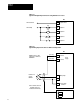
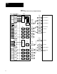
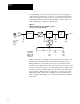
Figure 4.7
T
ypical 24 DC Digital Input Connections Using External Power Source
47
48
49
50
51
TB3
24V DC Common
Digital Common
Digital In 1
Digital In 2
Digital In 3
Digital In 4
Stop
Jog 2
Start
Clear Faults
24V DC High
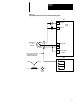
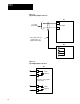
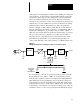
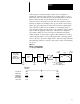
Figure 4.8
T
ypical Analog Input Connections for Unidirectional Operation
32
TB3
+10VDC
31
+
-
33
NOTE: Connect to either
terminal 31 or terminal 32,
NOT BOTH
Reference Pot
2.5 K Ω
Minimum
-10VDC
Power
Supply
Analog Input
Power Supply
Common
TB4
(See Note)
(See Note)
Connect shield to drive end
only. Other end is to be
insulated and left floating.