Allen Bradley Bulletin 1395 Discrete Adapter Board Catalog No.
Table of Contents Introduction . . . . . . . . . . . . . . . . . . . . . . . . . . . . . . . . . . . . 1 1 Manual Objectives . . . . . . . . . . . . . . . . . . . . . . . . . . . . . . . . . . . Documentation . . . . . . . . . . . . . . . . . . . . . . . . . . . . . . . . . . . . . Description of Equipment . . . . . . . . . . . . . . . . . . . . . . . . . . . . . . Adapter Specifications . . . . . . . . . . . . . . . . . . . . . . . . . . . . . . . . 1 1 1 1 1 1 1 2 Hardware Description . . . . . . . .
ii Table of Contents Troubleshooting and Maintenance . . . . . . . . . . . . . . . . . . . 6 1 Introduction . . . . . . . . . . . . . . . . . . . . . . . . . . . . . . . . . . . . . . . . Hard Faults . . . . . . . . . . . . . . . . . . . . . . . . . . . . . . . . . . . . . . . . Soft Faults . . . . . . . . . . . . . . . . . . . . . . . . . . . . . . . . . . . . . . . . . Warning Faults . . . . . . . . . . . . . . . . . . . . . . . . . . . . . . . . . . . . . Discrete Fault Messages . . . . . . . . . . .
Table of Contents Parameter 581 - [A> DAC Scale 4] 531 - [B> DAC Scale 4] . . . . Parameter 582 - [A> DAC Offset 4] 532 - [B> DAC Offset 4] . . . Parameter 583 - [A> Digital In 1] 533 - [B> Digital In 1] . . . . . . . Parameter 584 - [A> Digital In 2] 534 - [B> Digital In 2] . . . . . . . Parameter 585 - [A> Digital In 3] 535 - [B> Digital In 3] . . . . . . . Parameter 586 - [A> Digital In 4] 536 - [B> Digital In 4] . . . . . . . Parameter 599 - [A> DS: VERSION] 549 - [B> DS: VERSION] .
Chapter 1 Introduction Manual Objectives This manual contains the information necessary to help you perform the following functions on the Bulletin 1395 Discrete Adapter Board option: S Install Hardware S Verify correct Adapter Board input and output wiring S Configure the Adapter control to the Drive and its application This manual is intended for use by personnel familiar with the functions of solid state Drive equipment.
Chapter 1 Introduction Adapter Specifications A listing of board specifications and features is provided in Table 1.A. Any specifications pertaining directly to procedures detailed in this manual, will be stated where necessary in the manual. Table 1.A Discrete Board Specifications 1-2 Type Digital Inputs Use 24V DC or 120V AC, 10mA. NOTE: A separate board and part number is used for each voltage rating. Discrete Outputs Dry relay contacts rated at 0.6 Amps at 125V AC or 2.0 Amps at 30V DC.
Chapter 2 Hardware Description Chapter Objective Chapter 2 contains a general description of the major hardware components of the Discrete Adapter Board. It is not intended to be an all encompassing technical description of each hardware component. This chapter provides basic information to help you: S Identify the discrete board input configuration. S Understand the hardware requirements necessary to interface the Discrete board with peripheral devices.
Chapter 2 Hardware Description Analog Inputs The Discrete card contains four programmable 12-bit analog to digital inputs. These inputs allow a ± 10V DC analog signal to be converted to a ± 2048 digital signal, thus providing 4.88 millivolts per bit resolution. Through programming of associated Scale and Offset parameters the effective range of the converted signal can be extended to ± 32767. The converted analog signal can be used to control any of the 1395 run-time parameters.
Chapter 2 Hardware Description Board Hardware Configuration There are two board configuration options available for the Discrete Adapter Board I/O, 120V AC or 24V DC. The 120V AC Adapter Board configuration has a bank of four two watt resistors located directly above J3. These resistors drop the 120V AC down, and it is then sent through a rectifier and opto-isolator. The 24V DC version also has a bank of smaller resistors.
Chapter 2 Hardware Description Figure 2.
Chapter 2 Hardware Description Table 2.A Discrete Adapter Board Connections Conn J1 Type 60 Pin Ribbon Purpose Connection to Main Control Board J3 12 Discrete Wire Connection for Digital I/O Hardware Devices via TB32 terminals 43 - 52. J4 20 Discrete Wire Connection for Analog I/O Hardware Devices via TB3 terminals 23 - 42. J6 9 Pin Ribbon Serial I/O (Not currently used) Table 2.
Chapter 3 Control Description Introduction Chapter 3 contains a general description of the 1395 Discrete Adapter Board program. This description is intended to provide sufficient background information to support other procedures in this manual, and to help you to: S Understand how to configure the board. S Understand how to interface the board with discrete I/O. S Understand how to configure the Analog I/O for any application.
Chapter 3 Control Description Table 3.
Chapter 4 Installation Introduction This chapter is a detailed procedure for the proper installation and electrical interconnection of the Bulletin 1395 Discrete Adapter Board. Procedures you will perform in this chapter include: S Verification of proper unpacking and inspection S Verification of proper mounting S Verification of proper wiring Receiving It is your responsibility to thoroughly inspect the equipment before accepting shipment from the freight company.
Chapter 4 Installation If the board will not be installed when it is unpacked, it should be stored in a clean dry place in the anti-static bag. The storage temperature must be between 0°C (32°F) and +60°C (140°F) with a maximum humidity of 95% non-condensing, to guard against damage to temperature sensitive components. Mounting On 1 – 100 HP 230V and 2 – 200 HP 460V the Discrete Adapter Board is mounted on the front of the swing out panel (refer to system drawings.
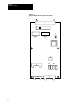
Chapter 4 Installation Figure 4.1 Discrete Adapter Board Location Discrete Adapter Board 1 30 HP, 230VAC 2 60 HP, 460VAC Discrete Adapter Board 40 100 HP, 230VAC 75 200 HP, 460VAC 125 300 HP, 230VAC 250 600 HP, 460VAC AB0727A Connections to Drive The Discrete Adapter Board can be connected to either Microbus Port A or B on the Drive through a ribbon cable connector J1 located at the top of the board. Connection to TB3 is made through two connectors, J3 and J4.
Chapter 4 Installation Figure 4.2 Connection of External Devices to the 1395 Drive Main Control Board J7 Port A or Port B Adapter Board Adapter Board Terminals 23 - 52 Terminals 23 - 52 J6 TB3 Terminals 1-22 Wiring to External Devices Wiring to External Devices External wiring is connected to the terminal block at the bottom of the 1395 enclosure. Terminals 23 through 52 are reserved for wiring the Discrete Adapter board to external I/O devices.
Chapter 4 Installation Figure 4.
Chapter 4 Installation Figure 4.
Chapter 4 Installation Figure 4.5 Typical 115 VAC Digital Input Connections Using Internal Power Source TB3 4 Stop 6 115V AC Common 47 Digital Common 48 Digital In 1 49 Digital In 2 50 Digital In 3 51 Digital In 4 Jog 2 Start Clear Faults Figure 4.
Chapter 4 Installation Figure 4.7 Typical 24 DC Digital Input Connections Using External Power Source TB3 24V DC Common 24V DC High Stop 47 Digital Common 48 Digital In 1 49 Digital In 2 50 Digital In 3 51 Digital In 4 Jog 2 Start Clear Faults Figure 4.8 Typical Analog Input Connections for Unidirectional Operation TB3 NOTE: Connect to either terminal 31 or terminal 32, NOT BOTH Reference Pot 2.
Chapter 4 Installation Figure 4.9 Typical Analog Input Connections for Bidirectional Operation TB3 F 32 +10VDC R Reference Pot 2.5 K Ω Minimum Power Supply 31 -10VDC + Analog Input - 33 Connect shield to drive end only. Other end is to be insulated and left floating.
Chapter 4 Installation Figure 4.10 Typical Analog Output Connections TB3 + 0 to ±10VDC 1mA maximum Analog Output Com Connect shield to drive end only. Other end is to be insulated and left floating. TB4 Figure 4.11 Typical Digital Output Connections TB3 45 Digital Output #1 46 Dry Contacts 0.
Chapter 5 Start Up Chapter Objectives Terminology This chapter will provide basic procedures that include initial adjustments and configuration of drive control. Procedures you will perform in this chapter include the following: S Establish Configuration Links between Drive and Discrete Board. S Program Discrete Adapter Set-Up Parameters. Parameter – Memory location used to store drive set-up data, or to monitor real time input or output information.
Chapter 5 Start Up Parameter Set Up Description After hard wiring the I/O to the Discrete Adapter board terminals, you must set up parameters in the drive using the Program Terminal to allow for data flow between the Discrete board and the drive. As was shown in Figure 4.4, each terminal has parameters associated with it. Set-Up parameters are used to program the Adapter board functions, and consist of Parameters 550 through 559 for Port A, and 500 through 549 for Port B.
Chapter 5 Start Up S The example shows two analog inputs connected to Parameters 400 and 401. In addition, these parameters are linked to drive Parameters 154 and 157 respectively. When an analog input is applied to analog input # 1, the signal is converted to a digital value and directed to Parameter 401. Since Parameter 401 is linked to Parameter 154 the digital value is directly transferred to Parameter 154 (External Velocity Ref). The same applies to all other analog inputs.
Chapter 5 Start Up Figure 5.
Chapter 5 Start Up Analog Input 1 and Analog Input 2 will be used in detailing the scaling and offset parameters. At Analog Input 1, between TB3 terminals 29 and 30, a potentiometer with a range of ± 10 V DC has been connected. Parameter 401 has been linked to Parameter 154 (Velocity Reference) in the drive, which gives the potentiometer control of the external velocity reference. To calibrate the pot to control 100% base speed in both directions, the scaling parameter must be adjusted.
Chapter 5 Start Up As seen in Figure 5.3, the offset voltage adds the corresponding digital value to the range. In this case, an offset of –5 volts adds a digital value of –1024 to the range. This causes 0 volts on the potentiometer to register as –1024 digital internal to the Drive. This can then be scaled so that 0 volts sends a digital value of –4096 for –100% Torque. Figure 5.
Chapter 5 Start Up Analog Output 1 and Analog Output 2 will be used as examples in detailing the scaling and offset parameters. At Analog Output 1, a meter with a range of 0 to 10 V DC has been connected. Parameter 451 has been linked to Parameter 106, Velocity Feedback. In order for the meter to indicate speed in both directions, the scale and offset parameters must be adjusted (see Figure 5.4). Working in the opposite direction as the analog inputs, apply the scaling factor first.
Chapter 5 Start Up As shown in Figure 5.5, another 0 to 10V DC meter is connected to Digital-To-Analog (D/A) output number 2. In this example, Parameter 452 which feeds the D/A is linked to drive Parameter 112, Armature Current Feedback. In this example we assume that armature Current Feedback will vary between 0% and 200% rated current. This means the drive digital signal will vary between 0 and 8192 and the D/A signal must vary between 0 and 2048 for a 0 to 10V DC output.
Chapter 6 Troubleshooting and Maintenance Introduction This section describes the Discrete adapter board fault diagnostics and how they are processed by the 1395 Drive. All Adapters provide initial fault handling based on conditions within their environment, and then signal the 1395 which provides further disposition based on system requirements. Faults are divided into three categories as described below. Hard Faults Hard Faults are non-recoverable.
Chapter 6 Troubleshooting and Maintenance Discrete Fault Messages The fault messages available on the Discrete Adapter Board are: S DS-01-DISCRETE OK Indicates no faults are present in the Adapter. S DS-31-ILLEGAL FAULT – Hard Fault Indicates an Internal Adapter error. Replace Discrete Adapter. S DS-54-DP HANDSHAKE – Soft Fault The 1395 Main Computer Board is no longer maintaining communications with the Adapter through Dual-Ported RAM. Ensure proper connection to Microbus interface.
Chapter 7 Periodic Maintenance Preventive Maintenance ATTENTION: Servicing energized industrial control equipment can be hazardous. Severe injury or death can result from electrical shock, burn, or unintended actuation of controlled equipment. Recommended practice is to disconnect and lock out control equipment from power sources, and allow stored energy in capacitors to dissipate, if present.
Chapter 7 Periodic Maintenance ATTENTION: Use of other than factory recommended test equipment for solid state controls may result in damage to the control or test equipment or unintended actuation of the controlled equipment. Static Sensitive Items – While performing maintenance on the 1395 Drive and the Discrete Adapter, special precautions must be observed in handling or touching certain static sensitive components in the cabinet.
Chapter 8 Parameter Table Chapter Objective This chapter contains the information required to assist the user in programming the drive for a specific application after initial start-up. Drives are shipped programmed with default values and are preconfigured for the options installed. Terminology Configuration – The process of linking Sink to Source parameters. For a description of configuration, refer to Chapter 5 in this manual.
Chapter 8 Parameter Table Parameter – Memory location used to store drive data. Each parameter is given a number called the parameter number. The parameter value may be specified in decimal, or in hexadecimal. When specified in hexadecimal, the word “Hex” will appear after the parameter value. Source Parameter – Fast parameter used as a source of data. Sink Parameter – Fast parameter used to receive data input. Parameter Table Table 8.
Chapter 8 Parameter Table Function – Indicates the related control function for the parameter. Port – Indicates port that parameter is associated with. Table 8.
Chapter 8 Parameter Table Table 8.A (cont.
Chapter 8 Parameter Table Table 8.A (cont.
Chapter 8 Parameter Table Parameter Descriptions This section provides you with a description of the parameters in the Bulletin 1395 Discrete adapter. Information is provided in the following format: Parameter – AAA [ Parameter Name ] – BBB [ Parameter Name ] Use: Program Terminal Units: Maximum Value: Minimum Value: Default Value: Description: A description of the information you will find in each category is provided here: Parameter AAA – The parameter number if the adapter is installed in port A.
Chapter 8 Parameter Table Configuration Parameters This section describes for you in detail each of the Configuration parameters available on the Discrete Adapter Board. All Configuration parameters are 16-bit words. In order for a Configuration parameter to affect system operation, it’s source and/or destination must be programmed in the 1395.
Chapter 8 Parameter Table Parameter 403 - [A > Analog In 3] 303 - [B > Analog In 3] Use: Digital value of Analog Input 3 Signal Program Terminal Units: None Minimum Value: –32767 Maximum Value: 32767 Default Value: None Description: This parameter is a Fast Source used to convert a ± 10V DC signal to a ± 32767 digital value. This digital value can then be linked to one of the drive input parameters such as Velocity Reference, Torque Reference, Process Trim Reference, etc.
Chapter 8 Parameter Table Parameter 451 - [A > Analog Out 1] 351 - [B > Analog Out 1] Use: Digital Value of Analog Output 1 Signal Program Terminal Units: None Minimum Value: –32767 Maximum Value: 32767 Default Value: None Description: This parameter is a Fast Sink which converts a ± 32767 digital value to a ± 10V DC output. This digital value can then be linked to one of the drive output parameters such as Velocity Feedback, Torque Command, Flux Command, etc.
Chapter 8 Parameter Table Parameter 454 - [A > Analog Out 4] 354 - [B > Analog Out 4] Use: Digital Value of Analog Output 4 Signal Program Terminal Units: None Maximum Value: 32767 Minimum Value: –32767 Default Value: None Description: This parameter is a Fast Sink which converts a ± 32767 digital value to a ± 10 VDC output. This digital value can then be linked to one of the drive output parameters such as Velocity Feedback, Torque Command, Flux Command, etc.
Chapter 8 Parameter Table Parameter 552 - [A > ADC Scale 2] 502 - [B > ADC Scale 2] Use: Scale factor for Analog Input 2 Program Terminal Units: None Minimum Value: –16 Maximum Value: +16 Default Value: 1 Description: This parameter determines the scale factor or Gain for Analog Input 2. A ± 10V DC signal applied to Analog Input 2 is converted to a ± 2048 digital value used by the drive.
Chapter 8 Parameter Table Parameter 555 - [A > ADC Offset 3] 505 - [B > ADC Offset 3] Use: Offset for Analog Input 3 Units: Volts Minimum Value: –20 VDC Maximum Value: +20 VDC Default Value: 0V DC Description: This parameter determines the offset applied to the raw Analog Input 3 value before the Scale Factor is applied. This allows the User to shift the range of the analog input.
Chapter 8 Parameter Table Parameter 558 - [A> Digital Out 1] 508 - [B> Digital Out 1] Use: Maps Digital Output 1 Program Terminal Units: None Maximum Value: 15 Minimum Value: 0 Default Value: 10 Description: This parameter has a range of 0 to 15. It establishes which bit of Discrete Output parameter 450/350 controls the Output 1 relay. When the bit is set the relay contact closes.
Chapter 8 Parameter Table Parameter 576 - [A> DAC Offset 1] 526 - [B> DAC Offset 1] Use: Offset for Analog Output 1 Program Terminal Units: Volts Minimum Value: –20V DC Maximum Value: +20V DC Default Value: 0 Description: This parameter determines the offset applied to the raw Analog Output 2 value after the Scale Factor is applied. This allows a shift in the range of the analog output.
Chapter 8 Parameter Table Parameter 579 - [A> DAC Scale 3] 529 - [B> DAC Scale 3] Use: Scale for for Analog Output 3 Program Terminal Units: None Minimum Value: –1 Maximum Value: +1 Default Value: +1 Description: This parameter determines the scale factor or Gain for Analog Output 3. A ± 32767 digital value from the drive is converted to a ± 10V DC signal. Before the digital value is converted the Scale Factor is applied, thus allowing an effective digital range of ± 2048 (32767/16 = 2048 = 10V DC).
Chapter 8 Parameter Table Parameter 582 - [A> DAC Offset 4] 532 - [B> DAC Offset 4] Use: Offset for Analog Output 4 Program Terminal Units: Volts Minimum Value: –20V DC Maximum Value: +20V DC Default Value: 0V DC Description: This parameter determines the offset applied to the raw Analog Output 4 value after the Scale Factor is applied. This allows the User to shift the range of his analog output.
Chapter 8 Parameter Table Parameter 585 - [A> Digital In 3] 535 - [B> Digital In 3] Use: Maps Digital Input 3 Program Terminal Units: None Minimum Value: 0 Maximum Value: 15 Default Value: 12 Description: This parameter has a range of 0 to 15. It establishes which bit of the Digital Input parameter is affected by Digital Input 3. Connecting Digital Input 3 (Terminal TB3 – 50) to Digital Common (TB3 – 47) will cause the bit specified by this parameter to be set to 1.
Publication 1395-5.12 February, 1995 (Supercedes May, 1994) P/N 155258 Copyright 1996, Allen Bradley Company, Inc.