
Reference Adapter for RTP Applications User Manual

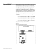
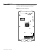
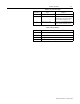

Table Of Contents
- Front Cover
- Important User Information
- Table of Contents
- Preface
- Who Should Use This Manual
- Purpose of This Manual
- Safety Precautions
- Contents of This Manual
- Related Documentation
- Information on the Intelligent Terminal System (ITS)
- Bulletin 1300 Intelligent Terminal System Documentation Set
- Allen-Bradley offers support services worldwide, with Sales/Support Offices, authorized distribut...
- Contact your local Allen-Bradley representative for:
- If you need to contact Allen-Bradley for technical assistance, please review the product and trou...
- Chapter 1
- Chapter 2
- Chapter 3
- Chapter 4
- Chapter 5
- Chapter Content
- 1. These steps should already have been performed on a custom Drive manufactured and shipped as a...
- 2. If a Drive that has already been installed is receiving a Digital Reference Adapter Board as a...
- 3. If for any reason a given Drive loses the EE memory information, it will also be necessary to ...
- 4. Should there be a need to check or download parameters to the Drive, use of the ITS device wil...
- 1. Establish Configuration Links between Drive and the Digital Reference Adapter Board.
- 2. Program Digital Reference Adapter Set-Up Parameters.
- Terminology
- Parameter Set-Up Description
- Example Start-Up Configuration (Linking)
- Digital Input/Output Set-up
- Analog Input/Output Set-up
- Configuration Links Set-up
- Chapter Content
- Chapter 6
- Introduction
- 1. Hard Faults Hard Faults are nonrecoverable. That is, the 1395 Drive must either be RESET or PO...
- 2. Soft Faults Soft Faults occur when an Adapter Board detects a condition which may result in un...
- 3. Warning Faults Conditions detected within the system that may produce Soft Faults if the condi...
- Digital Reference Fault Messages
- Adapter Troubleshooting
- Introduction
- Chapter 7
- Chapter 8
- Index
- Back Cover

Publication 1395-RTP-5.2 - September 1997
2-4 Hardware Description
Digital Outputs
Five programmable solid state digital outputs are provided. Normally,
they are 24V DC outputs, but are convertible with a panel mounted
120V AC, I/O module. By default, they are connected to the internal
programmed logic software for the application specific design, but are
also programmable to any of the 16 Logic Status Bits. All five outputs
are LED indicated for high level visibility.
When used in a RTP application, the following outputs apply:
• Digital Output 1 is normally the SPEED MATCH Output.
• Digital Output 2 is normally the READY Output.
• Digital Output 3 is normally the BELT EMERGENCY
BRAKE Output.
The final two outputs are normally not wired to interconnecting
circuitry, but instead are used as additional aids for setup and
troubleshooting.
• Digital Output 4 is normally the Dancer center position logic.
• Digital Output 5 is normally the Dancer web out position
logic.
Connector J3 is used to complete the interconnection for the digital
outputs between the Adapter Board and the Terminal Block (TB-3),
which is used to make the external connections.
• J3-09 to TB3-54 Digital Output 1
• J3-08 to TB3-55 Digital Output 2
• J3-07 to TB3-56 Digital Output 3
• J3-06 to TB3-57 Digital Output 4
• J3-05 to TB3-58 Digital Output 5
• J3-02 to TB3-61 +24V DC ISOL
• J3-01 to TB3-62 24V DC COMMON