
Reference Adapter for RTP Applications User Manual

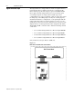

Table Of Contents
- Front Cover
- Important User Information
- Table of Contents
- Preface
- Who Should Use This Manual
- Purpose of This Manual
- Safety Precautions
- Contents of This Manual
- Related Documentation
- Information on the Intelligent Terminal System (ITS)
- Bulletin 1300 Intelligent Terminal System Documentation Set
- Allen-Bradley offers support services worldwide, with Sales/Support Offices, authorized distribut...
- Contact your local Allen-Bradley representative for:
- If you need to contact Allen-Bradley for technical assistance, please review the product and trou...
- Chapter 1
- Chapter 2
- Chapter 3
- Chapter 4
- Chapter 5
- Chapter Content
- 1. These steps should already have been performed on a custom Drive manufactured and shipped as a...
- 2. If a Drive that has already been installed is receiving a Digital Reference Adapter Board as a...
- 3. If for any reason a given Drive loses the EE memory information, it will also be necessary to ...
- 4. Should there be a need to check or download parameters to the Drive, use of the ITS device wil...
- 1. Establish Configuration Links between Drive and the Digital Reference Adapter Board.
- 2. Program Digital Reference Adapter Set-Up Parameters.
- Terminology
- Parameter Set-Up Description
- Example Start-Up Configuration (Linking)
- Digital Input/Output Set-up
- Analog Input/Output Set-up
- Configuration Links Set-up
- Chapter Content
- Chapter 6
- Introduction
- 1. Hard Faults Hard Faults are nonrecoverable. That is, the 1395 Drive must either be RESET or PO...
- 2. Soft Faults Soft Faults occur when an Adapter Board detects a condition which may result in un...
- 3. Warning Faults Conditions detected within the system that may produce Soft Faults if the condi...
- Digital Reference Fault Messages
- Adapter Troubleshooting
- Introduction
- Chapter 7
- Chapter 8
- Index
- Back Cover

Publicaton 1395-RTP-5.2 - September 1997
Introduction 1-3
Specifications
The following is a listing of board specifications and features. Any
specifications pertaining directly to procedures detailed in this
manual are presented when necessary.
Digital Reference Input – This is the current source and sink input
for high common mode noise immunity with nominal 5V DC or 12V
DC interface (internal hardware configurable) and ±10 mA nominal
current source/sink requirements. A typical application utilizes a
75174 quad driver integrated circuit mounted on either an encoder
driver module (available from Allen-Bradley) or in the customer's
interface circuitry. The hardware is configured for 5V DC inputs for
RTP Unwind Drive applications.
Digital Inputs – These inputs are 24V DC nominal; 18V DC
minimum, 28V DC maximum; 10 mA nominal.
NOTE: A separate panel mounted 120V AC, I/O module is used as
an interface to satisfy the 120V AC voltage rating.
Discrete Outputs – These outputs are 24V DC nominal; current
sourcing type driver; diode clamped for inductive load; 18V DC
minimum, 28V DC maximum; 1.5V DC saturation, 100 mA
maximum load.
NOTE: A separate panel mounted 120V AC, I/O module is used as
an interface to satisfy the 120V AC voltage rating.
Analog Inputs – These inputs are 0 to ±10V DC, differential input
impedance – Differential > 1Meg Ohm; 20K Ohms (single ended to
analog common).
Analog Outputs – These outputs are -10V DC to +10V DC, 2.5 mA
maximum. Output impedance – 200 Ohms.
Power Supply – The power supply voltage is +10V DC, 4 mA
maximum -10V DC, 4mA maximum Firmware Version – The
firmware version is 3.xx or 4.xx.