
Reference Adapter for RTP Applications User Manual

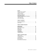
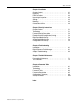
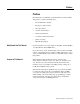
Table Of Contents
- Front Cover
- Important User Information
- Table of Contents
- Preface
- Who Should Use This Manual
- Purpose of This Manual
- Safety Precautions
- Contents of This Manual
- Related Documentation
- Information on the Intelligent Terminal System (ITS)
- Bulletin 1300 Intelligent Terminal System Documentation Set
- Allen-Bradley offers support services worldwide, with Sales/Support Offices, authorized distribut...
- Contact your local Allen-Bradley representative for:
- If you need to contact Allen-Bradley for technical assistance, please review the product and trou...
- Chapter 1
- Chapter 2
- Chapter 3
- Chapter 4
- Chapter 5
- Chapter Content
- 1. These steps should already have been performed on a custom Drive manufactured and shipped as a...
- 2. If a Drive that has already been installed is receiving a Digital Reference Adapter Board as a...
- 3. If for any reason a given Drive loses the EE memory information, it will also be necessary to ...
- 4. Should there be a need to check or download parameters to the Drive, use of the ITS device wil...
- 1. Establish Configuration Links between Drive and the Digital Reference Adapter Board.
- 2. Program Digital Reference Adapter Set-Up Parameters.
- Terminology
- Parameter Set-Up Description
- Example Start-Up Configuration (Linking)
- Digital Input/Output Set-up
- Analog Input/Output Set-up
- Configuration Links Set-up
- Chapter Content
- Chapter 6
- Introduction
- 1. Hard Faults Hard Faults are nonrecoverable. That is, the 1395 Drive must either be RESET or PO...
- 2. Soft Faults Soft Faults occur when an Adapter Board detects a condition which may result in un...
- 3. Warning Faults Conditions detected within the system that may produce Soft Faults if the condi...
- Digital Reference Fault Messages
- Adapter Troubleshooting
- Introduction
- Chapter 7
- Chapter 8
- Index
- Back Cover

Publication 1395-RTP-5.2 - September 1997
1-2 Introduction
• Five Discrete Outputs – Three outputs are application
dedicated, with outputs #4 & #5 being used only as indication
of dancer position. With the APCS, utilized outputs are 24V
DC, but can be converted using a panel mounted 120V AC,
I/O module for the MPCS application. The outputs are
connected by default to the internal programmed logic
software for the specific RTP Unwind Drive application, but
canalsobeprogrammedtoanyofthe16logicstatusbits.All
five outputs utilize LED indicators for high output level
visibility.
• Two Analog Inputs – The Analog #1 input is application
dedicated for the dancer potentiometer input, and Analog #2
is configurable for adjustable auto slack or emulated speed
reference input. Both inputs have special digitally
programmable analog offset and controlled variable analog
gain adjustments prior to being multiplexed into the analog to
digital converter. In the RTP Unwind Drive application,
Channel 1 is configured by default to a special dancer
potentiometer input. The inputs can also be configured to
represent any of the Bulletin 1395 signal inputs or the input
of another Digital Reference Adapter Board. These inputs
also employ programmable digital gain and digital offset
which provides maximum interface flexibility.
• Two Analog Outputs – Neither output is application
dedicated, but they can be configured to represent any of the
Bulletin 1395 signal outputs or the output of another Digital
Reference Adapter Board. The analog outputs can be used as
an effective troubleshooting aid to evaluate an internal digital
variable such as line speed reference (Parameter 403) or
process trim reference (Parameter 401). These outputs also
employ programmable digital gain and digital offset which
provides maximum interface flexibility.
• Proportional/Integral Amplifier – A P/I Regulator module
with an added feature of separate integral loop clamps was
included as a preregulator for the dancer potentiometer. In
addition, the regulator contains enable and disable handling
similar to the Process Trim Regulator located on the Bulletin
1395 Main Control Board.
• DC Power Supply – A ±10V DC Power Supply is provided
to power potentiometers connected to the analog inputs.
• LED Indicators – The board employs 19 green LED
indicators. Fifteen are used for digital I/O; one indicates that
the external 24V DC supply is functioning; two are used for
the internal ±12V DC analog supplies; and one indicates that
the +5V DC supply and the microprocessor are both
functioning.