Allen-Bradley Digital Reference Adapter for RTP Applications (Bulletin 1395) User Manual
Important User Information Because of the variety of uses for the products described in this publication, those responsible for the application and use of this control equipment must satisfy themselves that all necessary steps have been taken to assure that each application and use meets all performance and safety requirements, including any applicable laws, regulations, codes and standards.
Table of Contents Preface Who Should Use This Manual. . . . . . . . . . . . . . . . . . . . . . . . Purpose of This Manual . . . . . . . . . . . . . . . . . . . . . . . . . . . Safety Precautions . . . . . . . . . . . . . . . . . . . . . . . . . . . . . . . Contents of This Manual. . . . . . . . . . . . . . . . . . . . . . . . . . . Related Documentation . . . . . . . . . . . . . . . . . . . . . . . . . . . Common Techniques Used in This Manual . . . . . . . . . . . . Product Receiving. . . . . . . . . . .
Table of Contents Chapter 4 Installation Chapter Content . . . . . . . . . . . . . . . . . . . . . . . . . . . . . . . . . Receiving . . . . . . . . . . . . . . . . . . . . . . . . . . . . . . . . . . . . . . ESD Precautions . . . . . . . . . . . . . . . . . . . . . . . . . . . . . . . . Unpacking & Inspection . . . . . . . . . . . . . . . . . . . . . . . . . . . Storage . . . . . . . . . . . . . . . . . . . . . . . . . . . . . . . . . . . . . . . . Mounting . . . . . . . . . . . . . . . . . . . . . . . .
Preface Preface Read this preface to familiarize yourself with the rest of the manual. This preface covers the following topics: Who Should Use This Manual • who should use this manual • the purpose of this manual • safety precautions • contents of this manual • related documentation • conventions used in this manual • product receiving • Allen-Bradley support Use this manual if you are responsible for installing an Allen-Bradley 1395 Reel Tension Paster (RTP) Drive.
P-2 Preface Safety Precautions The following general precautions apply to Bulletin 1395 Drives and to RTP applications: ! ATTENTION: Only those familiar with the RTP system, the products used in the system, and the associated machinery should plan or implement the installation, startup, and future maintenance of the system. Failure to comply can result in personal injury and/or equipment damage.
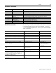
Preface P-3 Contents of This Manual Chapter Title Contents Preface Purpose, background, and scope of this manual 1 Introduction Description of equipment and specifications 2 Hardware Description Board functionality and descriptions of I/O 3 Control Description State diagrams, drive logic states, and drive reference control states 4 Installation Receiving, unpacking, inspection, storage, and connections to the drive 5 Start-Up Instructions Terminology, parameter set-up and configurations
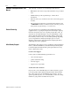
P-4 Preface Common Techniques Used in This Manual The following conventions are used throughout this manual: • Bulleted lists such as this one provide information, not procedural steps. • Numbered lists provide sequential steps or hierarchical information. • When we refer you to another location, the section name appears in italics.
Chapter 1 Introduction Description Of Equipment The Digital Reference Adapter Board provides an interface between an external device and the Bulletin 1395 Main Control Board. When used with the Reel-Tension-Paster (RTP) Drive, the Digital Reference Adapter Board allows the Drive to be commanded by a digital reference input signal from a single channel encoder or frequency generator whose shaft speed is equal to press speed.
1-2 Introduction Publication 1395-RTP-5.2 - September 1997 • Five Discrete Outputs – Three outputs are application dedicated, with outputs #4 & #5 being used only as indication of dancer position. With the APCS, utilized outputs are 24V DC, but can be converted using a panel mounted 120V AC, I/O module for the MPCS application.
Introduction Specifications 1-3 The following is a listing of board specifications and features. Any specifications pertaining directly to procedures detailed in this manual are presented when necessary. Digital Reference Input – This is the current source and sink input for high common mode noise immunity with nominal 5V DC or 12V DC interface (internal hardware configurable) and ±10 mA nominal current source/sink requirements.
1-4 Introduction This page intentionally left blank. Publication 1395-RTP-5.
Chapter 2 Hardware Description Chapter Content Board Function Chapter 2 contains a general description of the major hardware components of the Digital Reference Adapter Board. It is not intended to be an all encompassing technical description of each hardware component.
2-2 Hardware Description Digital Reference Input The Digital Reference Adapter Board contains one digital reference input which produces a digital speed reference command for the Drive which is proportional to the press speed of the RTP Unwind Drive application. The Adapter Board is set up for the line speed encoder input signal to be single channel, single edge, and is configurable for two edge or quadrature.
Hardware Description Digital Inputs 2-3 The Digital Reference Adapter Board contains ten programmable discrete inputs. The two standard configurations allow for either 120V AC signals or 24V DC signals. The nine inputs (#1 through #9) are connected by default to internal programmed logic software for the RTP Unwind Drive application design. The spare input is programmable to any of the 16 Logic Command Bits. All ten inputs utilize LED indicators for high input level visibility.
2-4 Hardware Description Digital Outputs Five programmable solid state digital outputs are provided. Normally, they are 24V DC outputs, but are convertible with a panel mounted 120V AC, I/O module. By default, they are connected to the internal programmed logic software for the application specific design, but are also programmable to any of the 16 Logic Status Bits. All five outputs are LED indicated for high level visibility.
Hardware Description Analog Inputs 2-5 The Digital Reference Adapter Board contains two programmable 12-bit, analog to digital inputs. These inputs allow a ±10V DC analog signal to be converted to a ±2048 digital signal, thus providing 4.88 millivolts per bit resolution. Both inputs have special digitally programmable analog offset adjustments and digitally controlled variable analog gain adjustments prior to being multiplexed into the analog to digital converter.
2-6 Hardware Description Firmware Location This Reference Adapter Board contains firmware version 4.xx. Figure 2-2 shows the component layout for the board, including physical location of the chips, major board hardware and test points. Figure 2.2 Component Layout for Reference Adapter Board J1 TP5 TP1 TP4 TP3 TP2 DS1 DS2 TP8 TP9 19 DS3 UMD3 3 2 1 TP10 1 2 3 J7 J6 TP11 TP12 TP14 DS4 DSI1 J2 Publication 1395-RTP-5.
Hardware Description 2-7 Table 1: Board Connections Connectors Type Purpose J1 60 pin Ribbon Connection to Main Control Board J2 20 pin Discrete Wire Connection for Analog I/O Hardware and Digital Reference Encoder Input Device via TB3 Terminals 23-42 J3 20 pin Discrete Wire Connection for Digital I/O Hardware Devices via TB3 Terminals 43-62 Table 2: Board Jumper Jumper Position/Purpose J4 Do Not Alter (used for testing and serial comm for debugger) J5 Factory Set, Do Not Alter (used for
2-8 Hardware Description This page intentionally left blank. Publication 1395-RTP-5.
Chapter 3 Control Description Chapter Content Parameter Overview Chapter 3 contains a general description of the 1395 Digital Reference Adapter Board program. This description is intended to provide sufficient background information to support other procedures in this manual and to assist the reader on: • Understanding how to configure the board • Understanding how to interface the board with discrete I/O. • Understanding how to configure the Analog I/O for the RTP application.
3-2 Control Description The Parameter number ranges for Port A are: State Diagrams • Port A Configuration Parameters (400 – 499) • Port A Set-Up Parameters (550 – 599) The internal programmable digital logic contains logic states or modes and control states or modes of operation which directly correlate to the RTP Unwind Drive application.
Control Description Drive Logic States Drive Reference Control States 3-3 DR = DRIVE READY – MODE 0 NR = NORMAL RUN – MODE 1 PC = PASTE CYCLE – MODE 2 DC = DECEL CYCLE – MODE 3 AC = ACCEL CYCLE – MODE 4 SM = SPEED MATCH – MODE 5 NS = NORMAL STOP – MODE 6 AST = AUTO SLACK TIGHT – MODE 7 ASL = AUTO SLACK LOOSE – MODE 8 RRDH = RUN REVERSE DANCER HIGH – MODE 9 WO = WEB OUT – MODE 10 RS = REGENERATIVE STOP – MODE 11 IDF = INTERNAL DRIVE FAULT – MODE 12 DNR = DRIVE NOT R
3-4 Control Description This page intentionally left blank. Publication 1395-RTP-5.
Chapter 4 Installation Chapter Content This chapter details the proper procedure for installation and electrical interconnection of the Digital Reference Adapter Board. Procedures performed in this chapter include: • Verification of proper unpacking and inspection • Verification of proper mounting • Verification of proper wiring Important: Normally, all installation and configuration requirements have been fulfilled when the product is shipped to the user.
4-2 Installation ESD Precautions ! ATTENTION: This Drive system contains ESD (electrostatic discharge) sensitive parts and assemblies. Static control precautions are required when installing, testing, or repairing this assembly. Component damage can result if ESD control procedures are not followed. If you are not familiar with static control procedures, refer to Allen-Bradley publication 8000-4.5.2, Guarding Against Electrostatic Damage or any other applicable ESD protection handbook.
Installation 4-3 Figure 4.1 Digital Reference Adapter Board Location – Port A Connections To Drive The Digital Reference Adapter Board is connected to Microbus Port A on the Drive through a ribbon cable connector J1 located at the top of the board. Connection to TB3 is made through two connectors, J2 and J3. Looking into the Drive, Port A is located on the left side, and Port B is located on the right. External wiring is connected to the terminal block at the bottom of the Drive enclosure.
4-4 Installation Figure 4.2 Connections to Terminal Block 3 (TB-3) on Drive Publication 1395-RTP-5.
Installation 4-5 Figure 4.3 Connections to Terminal Block 3 (TB-3) on Drive (con’t) Publication 1395-RTP-5.
4-6 Installation This page intentionally left blank. Publication 1395-RTP-5.
Chapter 5 Start-Up Instructions Chapter Content This chapter provides basic start-up procedures, including initial adjustments and configuration of the Drive control. Important: 1. These steps should already have been performed on a custom Drive manufactured and shipped as an RTP unwind Drive. 2. If a Drive that has already been installed is receiving a Digital Reference Adapter Board as an added feature, then all of the necessary configuration links, etc. will have to be made. 3.
5-2 Start-Up Instructions Source – Parameter which may be used as a source of data for output to a sink. Sink – Parameter which acts as an input of data from a source. Linking – The process of connecting a Sink Parameter to a Source Parameter. Parameter Set-Up Description After hard wiring the I/O to the Digital Reference Adapter Board terminals, parameters in the Drive must be set up using the Program Terminal to allow for data flow between the Board and the Drive.
Start-Up Instructions 5-3 The configuration shown provides the following setup: • The digital inputs are ONLY connected to the Drive logic state machine because their respective Set-up Parameter is set to 16. • The output of the Drive logic state machine and the Drive reference state machine are connected to Source Parameter 400, which in turn is linked to Parameter 151 (Logic Command 2).
5-4 Start-Up Instructions Digital Input/Output Set-up • The digital outputs 1, 2 and 3 are either receiving information via the logic status Parameter 100 or via the internal output digital logic depending on their respective parameter. In all cases, it is important to note that once a configuration link is established, data is transferred between the linked parameters automatically. Nothing further needs to be done. • Refer to Sheet 4 of Drawing 144041-18 located in the system binder.
Start-Up Instructions 5-5 The two default links are displayed by pressing the ENTER key, as follows: < 152 TO 200 > [18] [ENTER] < 250 TO 100 > [18] [ENTER] To add the new links proceed as follows: TYPE IN [450] [ENTER] (sink) TYPE IN [100] [ENTER] (source) Links Parameter 100 to 450 TYPE IN [151] TYPE IN [400] Links Parameter 400 to 151 [ENTER] (sink) [ENTER] (source) TYPE IN [153] TYPE IN [404] Links Parameter 404 to 153 [ENTER] (sink) [ENTER] (source) TYPE IN [154] TYPE IN [403] Links Parameter 403
5-6 Start-Up Instructions This page intentionally left blank. Publication 1395-RTP-5.
Chapter 6 Troubleshooting Introduction This chapter describes the Digital Reference Board fault diagnostics and how they are processed by the 1395 Drive. All Adapters provide initial fault handling based on conditions within their environment, and then signal the Drive which provides further disposition based on system requirements. Faults are divided into three categories. 1. Hard Faults Hard Faults are nonrecoverable.
6-2 Troubleshooting Publication 1395-RTP-5.2 - September 1997 • DR-70-DP HANDSHAKE – Soft Fault The 1395 Main Computer Board is no longer maintaining communications with the Adapter through Dual-Ported RAM. Ensure proper connection to Microbus interface. Power down and then reapply power. If not solved, replace Digital Reference Adapter. Reapply power; if not solved, reinstall original Adapter, replace Main Control Board and reapply power.
Troubleshooting • Adapter Troubleshooting 6-3 DR-83-Dancer Parameters – Soft Fault The dancer parameters corresponding to dancer center, dancer mid (midpoint between center and full), and dancer full (Parameters 560, 559, and 558 respectively) must be given values in the proper numeric sequence. Dancer full, Parameter 558, must be greater than Dancer mid, Parameter 559. Dancer mid must be greater than dancer center, Parameter 560.
6-4 Troubleshooting This page intentionally left blank. Publication 1395-RTP-5.
Chapter 7 Periodic Maintenance Preventative Maintenance ! ATTENTION: Servicing energized industrial control equipment can be hazardous. Severe injury or death can result from electrical shock, burn, or unintended actuation of controlled equipment. Recommended practice is to disconnect and lock out control equipment from power sources, and allow stored energy in capacitors to dissipate, if present.
7-2 Periodic Maintenance Guidelines for the Application, Installation and Maintenance of Solid State Control”. ! ATTENTION: Use of other than factory recommended test equipment for solid state controls may result in damage to the control or test equipment or unintended actuation of the controlled equipment. Static Sensitive Items – While performing maintenance, special precautions must be observed in handling or touching certain static sensitive components in the cabinet.
Chapter 8 Parameter Table Introduction This chapter contains materials intended to provide an easy reference condensed table of all configuration parameters and their specified uses. Terminology Configuration – The process of linking Sink to Source Parameters. For a description of configuration, refer to Chapter 5 in this manual. Configuration Parameters – Parameters used to transfer data between the Drive control and external devices. The Configuration Parameters are categorized into two types: 1.
8-2 Parameter Table Parameter – Memory location used to store Drive data. Each parameter is given a number called the parameter number. The parameter value may be specified in decimal, or in hexadecimal. When specified in hexadecimal, the word “Hex” will appear after the parameter value. Source Parameter – Fast parameter used as a source of data. Sink Parameter – Fast parameter used to receive data input.
Parameter Table 8-3 Table 1: Parameter Table Param No.
8-4 Parameter Table Table 1: Parameter Table (Continued) Param No.
Parameter Table Parameter Descriptions 8-5 This chapter provides a description of the parameters in the Bulletin 1395 Digital Reference Adapter. Information is provided in the following format: Parameter AAA [Parameter Name] Use: Program Terminal Units: Maximum Value: Minimum Value: Default Value: Description: Parameter AAA – The parameter number if the adapter is installed in Port A. [Parameter Name] – The parameter name as viewed on the program terminal.
8-6 Parameter Table Configuration Parameters This chapter describes in detail each of the Configuration parameters available on the Digital Reference Adapter Board. All Configuration parameters are 16-bit words. In order for a Configuration parameter to affect system operation, its source and/or destination must be programmed in the 1395.
Parameter Table 8-7 Parameter 403 – [A > Digital Reference Input (Whole)] Use: Digital value of the whole portion of the Digital Reference Input. Program Terminal Units: None Minimum Value: -32767 Maximum Value: 32767 Default Value: None Description: This parameter is a Fast Source used to connect the digital reference generated in the Adapter Board from the encoder input, to normally, the external velocity speed reference – whole part of the main control board.
8-8 Parameter Table Description: This parameter is a Fast Source used to transmit the status of the ninth and tenth digital inputs on the Adapter Board to the Drive. The ninth and tenth digital inputs can be mapped to any of the 16 bits in this parameter. Typically, this parameter is linked to one of the Logic Commands in the Drive which allows for Start, Stop, and Jog Control. The actual bit mapping is determined by the Set-Up Parameters explained in the next section.
Parameter Table 8-9 Parameter 412 – [A > Monitor Logic Mode] Use: Future use intended to monitor Drive Logic Modes Program Terminal Units: None Description: This parameter is a fast source that will be used to monitor the Logic Mode of the Drive when connected to an External Monitor/Maintenance System.
8-10 Parameter Table Set-Up Parameters This chapter describes the Set-Up parameters for the Digital Reference Adapter Board. The Set-Up parameters control how the Digital Reference Adapter Board manipulates data. Specifically they allow programming the use of the Digital inputs in the logic state machine and they alternatively program the bit positions for digital inputs and outputs along with scale factors and offsets for analog inputs and outputs.
Parameter Table 8-11 Parameter 552 – [A > ADC Scale #1] Use: Digital Scale Factor for Analog Input 1 Program Terminal Units: None Maximum Value: +16 Minimum Value: -16 Default Value: 1.10 Description: This parameter determines the digital scale factor or Gain for Analog Input 1.
8-12 Parameter Table Parameter 555 – [A > Analog Offset #2] Use: Analog Offset for Analog Input 2 Programming Terminal Units: Volts Maximum Value: +10V DC Minimum Value: -9.995V DC Default Value: 0V DC Description: This parameter is not used in the RTP Unwind Drive applications. This parameter determines the analog offset applied to the Analog Input #2 signal prior to the analog signal amplification. This allows the signal to be shifted close to zero volts prior to being amplified.
Parameter Table 8-13 Description: This parameter determines the dancer full position logic level for the Drive logic state machine. This is based upon the output of the analog to digital converter of analog input #1 prior to analog #1 being digitally offset and scaled. The output of the converter will be 0 to 2048 corresponding to 0.0 volts to ±0.61 volts, nominally, of Dancer potentiometer wiper voltage. This parameter sets the comparison value of input # 1 above which the logic symbol, DFP = 1.
8-14 Parameter Table Parameter 562 – [A> Max Press Reference RPM – Digital Reference] Use: Specifies the maximum RPM of the reference encoder. Program Terminal Units: RPM Maximum Value: 6000 Minimum Value: 0 Default Value: 2566 Description: This parameter specifies the maximum revolutions per minute of the digital reference encoder, or in this application, the magnetic pick-up. The sign of the parameter allows the sign inversion of the speed reference output to the main control board.
Parameter Table 8-15 Parameter 566 – [A > Velocity KP High – Speed Loop KP High Speed] Use: Specifies the value of KP, (Par. 660). Program Terminal Units: None Maximum Value: 1600 Minimum Value: 300 Default Value: 425 Description: This parameter specifies the value of proportional gain of the velocity loop for speeds above the switch point in RPM as determined by Parameter 569. Parameter 567 – [A> P/I Regulator Integral Gain] Use: Determines the proper integral gain of the digital reference regulator.
8-16 Parameter Table Parameter 570 – [A> Low Sum RRDH – Process Trim Low Sum RRDH] Use: Determines Process Trim Low Sum value dependent upon logic mode. Program Terminal Units: RPM Maximum Value: 0 Minimum Value: -100 Default Value: -20 Description: This parameter specifies the value of Process Trim Low Sum, Parameter 721, through velocity indirect Parameter 164. This sets Parameter 721 to a negative value when in logic mode 9, Run Reverse Dancer High, which allows the Drive to run in reverse at -20 RPM.
Parameter Table 8-17 Parameter 573 – [A > DR QUAD ENABLE – Digital Reference Input] Use: Sets the encoder type of reference input. Program Terminal Units: None Maximum Value: ON Minimum Value: OFF Default Value: OFF Description: This parameter, with Parameter 574, is used to setup the digital reference input for the type of signal being supplied. If this parameter is set the speed reference is a counting quad (4) edges on the digital reference input.
8-18 Parameter Table Parameter 580 – [A> Timer 1] Use: Specifies the timing value of timer 1. Program Terminal Units: Seconds Maximum Value: 2.0 Minimum Value: 2.0 Default Value: 2.0 NOT CHANGEABLE Description: This parameter specifies the amount of time in seconds required for Timer T1 in the Logic State Machine to time out. The default time is 2.0 seconds.
Parameter Table 8-19 Parameter 584 – [A> P/I Regulator Output Low Clamp] Use: Specifies the minimum value of the P/I Output. Program Terminal Units: None Maximum Value: 0 Minimum Value: -500 Default Value: -160 Description: This parameter specifies the minimum value that the P/I Regulator can operate to. Parameter 586 – [A> DAC Scale 1] Use: Offset for Analog Output 1 Program Terminal Units: None Maximum Value: +1 Minimum Value: -1 Default Value: .
8-20 Parameter Table Parameter 589 – [A> DAC Offset 2] Use: Offset for Analog Output 2 Program Terminal Units: Volts Maximum Value: +10V DC Minimum Value: -10V DC Default Value: 0V DC Description: This parameter is not used in the RTP Unwind Drive applications. This parameter determines the offset applied to the raw Analog Output 2 value after the Scale Factor is applied. This allows the User to shift the range of his analog output.
Parameter Table 8-21 Parameter 591 – [A> Digital Out 2] Use: Maps Digital Output 2 Program Terminal Units: None Maximum Value: 15 Minimum Value: 0 Default Value: 7 Description: This parameter has a range of 0 to 16. When the parameter is set to 16, the output bit is permanently assigned to the state machine logic which communicates with the main control board through configuration Parameter 450.
8-22 Parameter Table Parameter 593 – [A> Digital Out 4] Use: Maps Digital Output 4 Program Terminal Units: None Maximum Value: 16 Minimum Value: 0 Default Value: 16 Description: This parameter has a range of 0 to 16. When the parameter is set to 16 (the default), the output bit is permanently assigned to the State Machine Logic. The State Machine Logic communicates with the main control board through configuration parameter 450.
Parameter Table 8-23 Parameter 596 – [A> Logic Mode] Use: Maps Drive Logic State Machine Mode # Program Terminal Units: None Maximum Value: 0 Minimum Value: 0 Default Value: 0 READ ONLY PARAMETER Description: This parameter is used as a monitoring device only. The parameter is monitoring the Drive logic state machine mode number and displays the value.
8-24 Parameter Table This page intentionally left blank. Publication 1395-RTP-5.
Index A E Adapter Troubleshooting, 6-3 ESD Precautions, 4-2 Analog Input/Output Set-up, 5-4 Example Start-Up Configuration (Linking), 5-2 Analog Inputs, 1-2, 1-3, 2-5 Analog Outputs, 1-2, 1-3, 2-5 F Final Check Out, 7-2 B Firmware Location, 2-6 Board Features, 1-1 Board Function, 2-1 H Hard Faults, 6-1 C Hardware Description, 2-1 Configuration Links Set-up, 5-4 Configuration Parameters, 8-6 I Connections to Drive, 4-3 Installation, 4-1 Connections to Terminal Block 3 (TB-3) on Drive, 4-4,
I–2 Index P T P/I Amplifier, 1-2 Terminals, 7-1 Parameter Descriptions, 8-5 Terminology, 5-1, 8-1 Parameter Overview, 3-1 Tests & Records, 7-2 Parameter Set-Up Description, 5-2 Troubleshooting, 6-1 Parameter Table, 8-1, 8-2 Periodic Inspection, 7-1 Periodic Maintenance, 7-1 U Unpacking & Inspection, 4-2 Power Supply, 1-2, 1-3 Preventative Maintenance, 7-1 W Warning Faults, 6-1 R Receiving, 4-1 S Set-Up Parameters, 8-10 Soft Faults, 6-1 Solid State Devices, 7-1 Specifications, 1-3 Start-Up In
Publication 1395-RTP-5.2 - September 1997 p/n 146377 1997 Rockwell International. All Rights Reserved.