
Reference Adapter Board User guide
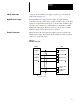
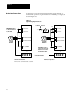
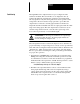
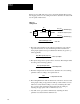
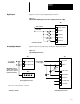
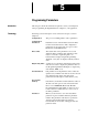


Table Of Contents

Chapter 4
Installation
4-7
24V DC Connection A properly sized 24V DC power supply is required to power the 24 volt
inputs. Refer to Figure 4.4.
Digtial Reference Input The Digital Reference Adapter Board contains one digital reference
command for the drive. The board is set up by default for the encoder input
signal to be single channel, dual edge (i.e. both the rising and falling edges
are used by the counting logic.). The hardware is configured for +5VDC
signal inputs with jumpers J6 and J7 in the 1-2 position. For a +12V DC
signal the jumpers must be placed in the 2-3 position.
Encoder Connection Figure 4.6 shows the typical encoder connection used as a signal for the
digital reference input. This encoder can be machine mounted or mounted
on the motor of the lead section.
Figure 4.6
Encoder
Connections
ENCODER CH B
23
24
25
26
TB3
ENCODER CH A
ENCODER CH A
ENCODER CH B
14
13
CHANNEL B
Encoder
CHANNEL A
CHANNEL A
CHANNEL B
+
C
POWER
SUPPL
Y
COMMON
+12V DC POWER
SUPPLY