
Reference Adapter Board User guide

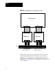
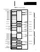
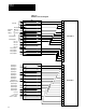
Table Of Contents
Chapter 4
Installation
4-6
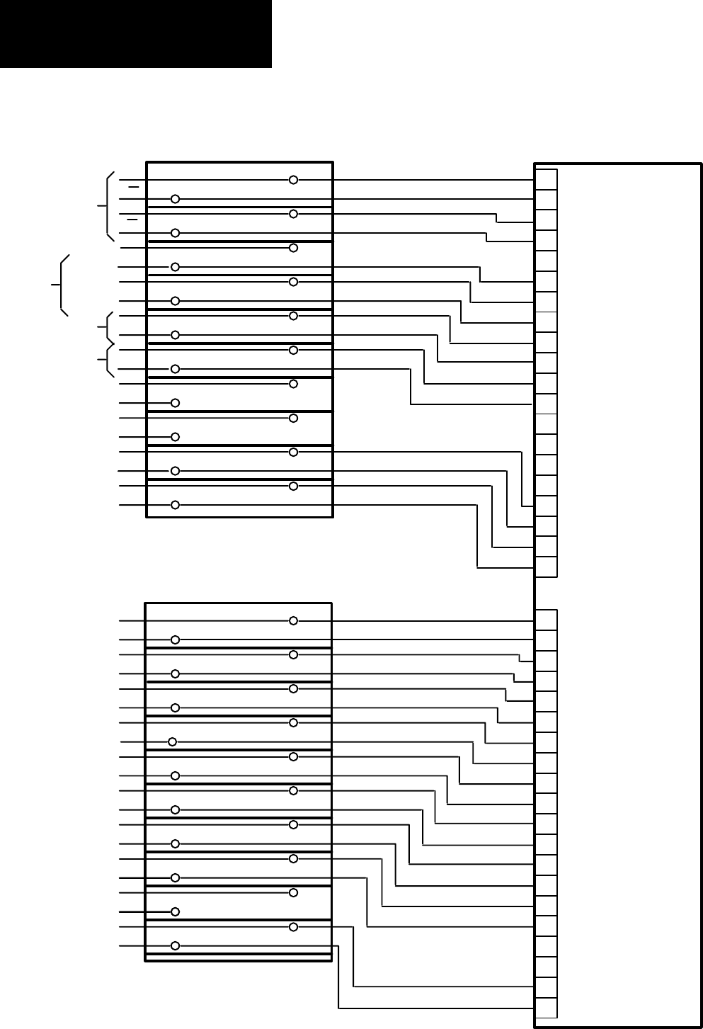
Figure 4.5
Hardware
Connection Diagram
19
18
17
16
20
15
14
13
12
11
10
Digital Ref Adapter
Analog I/O J2
8
7
6
5
9
4
3
2
1
19
18
17
16
20
15
14
13
12
11
10
8
7
6
5
9
4
3
2
1
TB3
23
24
25
26
28
27
29
30
32
31
34
33
35
36
38
37
40
39
41
42
44
43
46
45
47
48
50
49
51
52
54
53
56
55
57
58
60
59
62
61
TB3
Analog I/O J3
Encoder
A
A
B
B
+10
VDC
-10 VDC
Common
Reference
Power
Supply
Analog Input 1
Analog Input 2
Not
Used
Not Used
Not Used
Not Used
Analog Output 1
Analog Output 1
Analog Output 2
Analog Output 2
Out
Out
Com
Com
Digital Input 1
Digital Input 2
Digital Input 3
Digital Input 4
Digital Input 5
Digital Input 6
Digital Input 7
Digital Input 8
Digital Input 9
Digital Input 10
Digital Input Common
Digital Output 1
Digital Output 2
Digital Output 3
Digital Output 4
Digital Output 5
Not Used
Not Used
+24V DC ISOL
+24V DC Common
Not Used