
Reference Adapter Board User guide
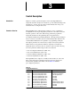
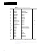
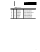
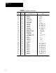
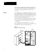

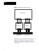
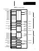
Table Of Contents
Chapter 4
Installation
4-3
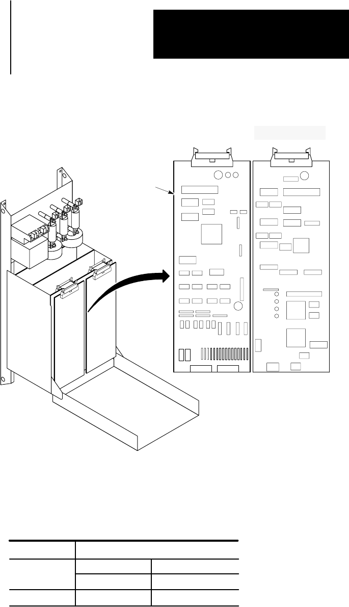
Figure 4.2
Digital
Reference Adapter Board Location
125 - 600HP
AB0730A
Digital Reference
Adapter Board
Jumper Settings The jumpers listed in Table 4.A need to be set for Encoder interface use.
Table 4.A
Encoder
Jumper Settings
Jumper
Encoder Output V
oltage
J6
J7
+5V DC +12V DC
1 - 2
1 - 2
2 - 3
2 - 3
Connections to Drive The Digital Reference Adapter Board will normally be connected to
Microbus Port A on the Drive through a ribbon cable connector J1 located
at the top of the board. The Digital Reference Adapter Board can however
be connected to either Microbus Port A or B on the Drive through ribbon
cable connector J1. Connection to TB3 is made through two connectors, J2
and J3. Looking into the Drive, Port A is located on the left side, and Port
B is located on the right as seen in Figure 4.3. The parameters used to
configure the Drive depend upon which port is utilized.