Allen Bradley Bulletin 1395 Digital Reference Adapter Board Catalog No.
Table of Contents Introduction . . . . . . . . . . . . . . . . . . . . . . . . . . . . . . . . . . . . 1 1 Manual Objectives . . . . . . . . . . . . . . . . . . . . . . . . . . . . . . . . . . . Description of Equipment . . . . . . . . . . . . . . . . . . . . . . . . . . . . . . Adapter Specifications . . . . . . . . . . . . . . . . . . . . . . . . . . . . . . . . 1 1 1 1 1 2 Hardware Description . . . . . . . . . . . . . . . . . . . . . . . . . . . . 2 1 General . . . . . . . . . . . . . . . . . . .
ii Table of Contents Start Up . . . . . . . . . . . . . . . . . . . . . . . . . . . . . . . . . . . . . . . 6 1 Introduction . . . . . . . . . . . . . . . . . . . . . . . . . . . . . . . . . . . . . . . . Terminology . . . . . . . . . . . . . . . . . . . . . . . . . . . . . . . . . . . . . . . . Parameter Set Up . . . . . . . . . . . . . . . . . . . . . . . . . . . . . . . . . . . Example Start Up Configuration . . . . . . . . . . . . . . . . . . . . . . . . . Digital Inputs & Outputs . . . . . . . . .
Chapter 1 Introduction Manual Objectives This manual contains the information necessary to allow you to perform the following functions on the Bulletin 1395 Digital Reference Adapter Board option: S Install Hardware S Verify correct Adapter Board input and output wiring. S Configure the Adapter control to the Drive and its application.
Chapter 1 Introduction S Five Discrete Outputs – These are 24 VDC outputs, and can be connected to any source parameter such as the logic status word. All five outputs are LED indicated for high input level visibility. S Two Analog Inputs – Both inputs have special digitally programmable analog offset adjustments and digitally controlled variable analog gain adjustments prior to being multiplexed into the analog to digital converter.
Chapter 2 Hardware Description General Chapter 2 contains a general description of the major hardware components of the Digital Reference Adapter Board. It is not intended to be an all encompassing technical description of each hardware component. This chapter provides basic information to help you: S Identify the Digital Reference Board input configuration. S Understand the hardware requirements necessary to interface the Digital Reference Board with peripheral devices.
Chapter 2 Hardware Description Digital Reference Input The Digital Reference Adapter Board contains one digital reference input which produces a digital reference command for the Drive. The Adapter Board is set up by default for the encoder input signal to be single channel, dual edge (i.e., both the rising edge and falling edge are used by the counting logic). The hardware is configured for 5 volt signal inputs with the jumpers J6 and J7 in the 1-2 position.
Chapter 2 Hardware Description Digital Outputs Five programmable solid state digital outputs rated 24VDC are provided. They can be connected to any source parameter such as the logic status word. All five outputs are LED indicated for high input level visibility. Connector J3 is used to make the interconnection for the digital outputs between the Adapter Board and the Terminal Block, TB-3, which is used to make the external connections.
Chapter 2 Hardware Description Connector J2 is used to make the interconnection for the analog outputs between the Adapter Board and the Terminal Block, TB-3, which is used to make the external connections. S TB3-39 Analog Output 1 S TB3-40 Analog Output 1 Common S TB3-41 Analog Output 2 S TB3-42 Analog Output 2 Common Firmware Location This board contains firmware version 1.xx. Figure 2.2 shows the physical location of the chips and also illustrates the microprocessor and other hardware on the board.
Chapter 2 Hardware Description Table 2.A Digital Reference Adapter Board Connections Connector Type J1 60 pin Ribbon J2 20 pin Discrete Wire Connection for Analog I/O Hardware and Digital Reference Encoder Input Device via TB3 terminals 23 - 42 J3 20 pin Discrete Wire Connection for Digital I/O Hardware devices via TB3 terminals 43 - 62 Purpose Connection to Main Control Board Table 2.
Chapter 3 Control Description Introduction Chapter 3 contains a general description of the 1395 Digital Reference Adapter Board. This description is intended to provide sufficient background information to support other procedures in this manual, and to help you to understand how to configure the board. Parameter Overview The Digital Reference Adapter Board contains two types of parameters, Configurable and Set-Up.
Chapter 3 Control Description Table 3.
Chapter 3 Control Description Table 3.
Chapter 3 Control Description Table 3.
Chapter 4 Installation Introduction This chapter is a detailed procedure for the proper installation and electrical interconnection of the Digital Reference Adapter Board. Procedures you will perform in this chapter include: S Verification of proper unpacking and inspection S Verification of proper mounting S Verification of proper wiring NOTE: Normally all installation and configuration requirements have been fulfilled when the product is shipped to the user in an integrated factory controller.
Chapter 4 Installation If the board will not be installed when it is unpacked, you must store it in a clean dry place in the anti-static bag. The storage temperature must be between 0°C (32°F) and +60°C (140°F) with a maximum humidity of 95% non-condensing, to guard against damage to temperature sensitive components. Mounting On 1 – 100 HP 230V and 2 – 200 HP 460V the Digital Reference Adapter Board is mounted on the front of the the swing out panel.
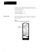
Chapter 4 Installation Figure 4.2 Digital Reference Adapter Board Location 125 - 600HP Digital Reference Adapter Board AB0730A Jumper Settings The jumpers listed in Table 4.A need to be set for Encoder interface use. Table 4.
Chapter 4 Installation Figure 4.3 Connection of the Digital Reference Adapter Board to Port A or B Main Control Board PORT A J7 ËËËËË ËËËËË ËËËËË ËËËËË J1 Adapter Board J2 J3 PORT B ËËËË ËËËË ËËËË ËËËË J6 J1 Adapter Board J2 J3 TB3 Terminals 1 - 22 Terminals 23 - 62 Wiring to External Devices Terminals 23 - 62 Wiring to External Devices External wiring is connected to the terminal block at the bottom of the 1395 enclosure.
Chapter 4 Installation Figure 4.
Chapter 4 Installation Figure 4.
Chapter 4 Installation 24V DC Connection A properly sized 24V DC power supply is required to power the 24 volt inputs. Refer to Figure 4.4. Digtial Reference Input The Digital Reference Adapter Board contains one digital reference command for the drive. The board is set up by default for the encoder input signal to be single channel, dual edge (i.e. both the rising and falling edges are used by the counting logic.).
Chapter 4 Installation Analog Input Connections Connections for velocity trim and reference inputs can be either uni- or bi-directional operation, using the internal drive ±10VDC power supply as shown in Figure 4.7. Figure 4.7 Typical Analog Input Connections TB3 TB3 Forward IMPORTANT: Connect to either terminal 28 or 29, Not Both 28 +10V DC P.S. 29 -10V DC P.S. Reverse R * R* R 28 +10V DC P.S. 29 -10V DC P.S. 31 EXT. VELOCITY REF. 32 EXT. VELOCITY REF. 33 P.S.
Chapter 4 Installation Tach Velocity The Digital Reference Adapter Board is not pre-configured for DC tachometer feedback. The user will have to reconfigure the drive by replacing the Trim Velocity Reference (parameter 161) with the Tach Velocity (parameter 156). The analog tachometer device generates a DC voltage that is direction sensitive and proportional to speed. The tach output must be connected to an analog input channel on the Discrete Adapter Board.
Chapter 4 Installation Figure 4.8 uses a l0k ohm resistor across the input channel. Rl represents the dropping resistor for the scaling network. To determine the value of Rl use the equation that follows. Figure 4.8 Scaling Circuit R1 Analog In (+) + TB3 33 10k Ohm Resistors 0.5W, 1% Tach 20k Adapter Board Input Impedance Analog In (-) - TB3 34 (Max Volts Output) x 6666 9V Tach Velocity (+) Tach Velocity (-) - 6666 = R1 3.
Chapter 4 Installation Digital Inputs Figure 4.9 shows a typical digital input connection. Figure 4.9 Typical 24V DC Digital Input Connections using External Power Supply TB3 24V DC Common* 24V DC High* Stop* Jog 2* Start* Clear Faults* 53 DIGITAL COMMON 43 DIGITAL IN 1 44 DIGITAL IN 2 45 DIGITAL IN 3 46 DIGITAL IN 4 * External to the Drive Analog/Digital Outputs Figure 4.10 shows typical analog and digital output connections. Figure 4.
Chapter 5 Programming Parameters Introduction This chapter contains the information required to assist you in Chapter 6 when programming the Digital Reference Adapter for your application. Terminology Following is a brief description of new terms and concepts covered in Chapter 5. Configuration Configuration Parameters The process of linking Sink to Source parameters. Parameters used to transfer data between the Drive Control and external devices.
Chapter 5 Programming Parameters Parameter Table Parameter Entry Information stored in the Drive which contains the parameter number, parameter data and all other information related to the specific parameter. Parameter Table Table of parameter entries for all Configuration and Setup parameters used in the drive. Source Fast parameter used as a source of data. Sink Fast parameter used to receive data input. Table 5.
Chapter 5 Programming Parameters Table 5.
Chapter 5 Programming Parameters Table 5.
Chapter 5 Programming Parameters Table 5.A Cont.
Chapter 5 Programming Parameters Configuration Parameters This reference section describes in detail each of the Configuration parameters available on the Digital Reference Adapter Board when installed in either Port A or Port B. The parameters for Port B are shown below the corresponding Port A parameters. All examples given are for Port A All Configuration parameters are 16 bit words.
Chapter 5 Programming Parameters Parameter 402 – [A > Analog In 2] Parameter 302 – [B > Analog In 2] Use : Digital value of Analog Input 2 Signal Programming Terminal units: None Minimum Value: –32767 Maximum Value: 32767 Default Value: None Description: This parameter is a Fast Source used to convert a ± 10V DC signal to a ±32767 digital value. This digital value can then be linked to one of the drive input parameters such as Velocity Reference, Process Trim Reference and Torque Reference.
Chapter 5 Programming Parameters Parameter 405 – [A > Dig Input 2] Parameter 305 – [B > Dig Input 2] Use : Status of Discrete Input Programming Terminal units: None Description: This parameter is a Fast Source used to transmit the status of the digital inputs on the Adapter Board to the drive. The ten digital inputs can be mapped to any of the 16 bits in this parameter. Typically, this parameter is linked to one of the Logic Commands in the drive which allows for Start, Stop and Jog Control.
Chapter 5 Programming Parameters Parameter 452 – [A > Analog Out 2] Parameter 352 – [B > Analog Out 2] Use : Digital value of Analog Output 2 Signal Programming Terminal units: None Minimum Value: –32767 Maximum Value: 32767 Default Value: None Description: This parameter is a Fast Sink used to convert a ±32767 digital value to a ± 10V DC output. This digital value can then be linked to one of the Drive input parameters such as Velocity Feedback, Armature Current feedback, Flux Command, etc.
Chapter 5 Programming Parameters Set Up Parameters Set-Up parameters control how the Digital Reference Adapter Board manipulates data. Parameters 550 through 592 are set-up parameters for a Digital Ref board installed in Port A. The parameters for Port B are shown below the corresponding Port A parameters. All examples given are for Port A. Specifically they allow programming the bit positions for digital inputs and outputs along with scale factors and offsets for analog inputs and outputs.
Chapter 5 Programming Parameters analog to digital converter. There, it is converted to a +2048 digital value prior to being digitally scaled, digitally offset and used by the drive. Before the digital value is displayed or transferred to the drive, the Scale Factor is applied, thus allowing an effective digital range of +32767(16 times 2048). The absolute digital value is clamped at 32767.
Chapter 5 Programming Parameters Parameter 555 – [A > Analog Offset 1] Parameter 505 – [B > Analog Offset 1] Programming Terminal units: Volts Minimum Value: – 10 VDC Maximum Value: + 10 VDC Default Value: 0.0 VDC Description: This parameter determines the analog offset applied to the Analog Input 1 signal prior to the analog signal amplification. This allows the signal to be shifted close to zero volts prior to being amplified.
Chapter 5 Programming Parameters Parameter 558 – [A > Digital Out 1] Parameter 508 – [B > Digital Out 1] Use : Maps Digital Output 1 Programming Terminal units: None Minimum Value: 0 (#1), 16 (#2) Maximum Value: 15 (#1), 31 (#2) Default Value: 10 Description: This parameter determines which bit of one of the two Digital Output fast parameters will control Digital Output 1. Entering a bit value of 0 – 15 will cause the Digital Output 1 (par 450) to control digital out 1.
Chapter 5 Programming Parameters Parameter 561 – [A > Digital Out 4] Parameter 511 – [B > Digital Out 4] Use : Maps Digital Output 4 Programming Terminal units: None Minimum Value: 0 (#1), 16 (#2) Maximum Value: 15 (#1), 31 (#2) Default Value: 8 Description: This parameter determines which bit of one of the two Digital Output fast parameters will control Digital Output 4. Entering a bit value of 0 – 15 will cause the Digital Output 1 (par 450) to control digital out 1.
Chapter 5 Programming Parameters Parameter 563 – [A > Digital Ref PPR] Parameter 513 – [B > Digital Ref PPR] Use : Specifies the pulse revolution of the reference encoder. Programming Terminal units: PPR Minimum Value: 100 Maximum Value: 32767 Default Value: 1024 Description: This parameter specifies the pulse per revolution of the digital reference encoder.
Chapter 5 Programming Parameters Parameter 567 – [A > One/Two/Quad] Parameter 517 – [B > One/Two/Quad] Use : Sets the encoder interface counting system. Programming Terminal units: None Minimum Value: 0 Maximum Value: 4 Default Value: 4 Description: This parameter is used to setup the digital reference input for the type of signal being supplied. The valid choices are: 1 = Single ended, one edge input, rising edge. 2 = Single edged, two edge input, rising and falling edge.
Chapter 5 Programming Parameters Parameter 575 – [A > DAC Scale 1] Parameter 525 – [B > DAC Scale 1] Use : Scale Factor for Analog Output 1 Programming Terminal units: None Minimum Value: –1 Maximum Value: +1 Default Value: +1 Description: This parameter determines the scale factor or gain for Analog Output 1. A +/– 32767 digital value from the drive is converted to a +/– 10V DC signal.
Chapter 5 Programming Parameters Parameter 583 – [A > Digital In 1] Parameter 533 – [B > Digital In 1] Use : Maps Digital Input 1 Programming Terminal units: None Minimum Value: 0 (#1), 16 (#2) Maximum Value: 15 (#1), 31 (#2) Default Value: 11 Description: This parameter performs two functions. It determines which bit of the two Digital Input Fast parameters will be controlled by Digital In 1.
Chapter 5 Programming Parameters Parameter 585 – [A > Digital In 3] Parameter 535 – [B > Digital In 3] Use : Maps Digital Input 3 Programming Terminal units: None Minimum Value: 0 (#1), 16 (#2) Maximum Value: 15 (#1), 31 (#2) Default Value: 12 Description: This parameter performs two functions. It determines which bit of the two Digital Input Fast parameters will be controlled by Digital In 3 (Terminal TB3-45).
Chapter 5 Programming Parameters Parameter 588 – [A > Digital In 6] Parameter 538 – [B > Digital In 6] Use : Maps Digital Input 6 Programming Terminal units: None Minimum Value: 0 (#1), 16 (#2) Maximum Value: 15 (#1), 31 (#2) Default Value: 8 Description: This parameter performs two functions. It determines which bit of the two Digital Input Fast parameters will be controlled by Digital In 6 (Terminal TB3-48).
Chapter 5 Programming Parameters Parameter 591 – [A > Digital In 9] Parameter 541 – [B > Digital In 9] Use : Maps Digital Input 9 Programming Terminal units: None Minimum Value: 0 (#1), 16 (#2) Maximum Value: 15 (#1), 31 (#2) Default Value: 1 Description: This parameter performs two functions. It determines which bit of the two Digital Input Fast parameters will be controlled by Digital In 9 (Terminal TB3-51).
Chapter 6 Start Up Introduction This chapter will provide you with basic procedures for initial adjustments and configuration of the Drive control. Procedures you will perform in this chapter include the following: S Verification of proper installation and wiring. S Configuration of the Drive Control for Digital Reference Adapter I/O. Terminology Parameter – Memory location used to store Drive set-up data, or to monitor real time input or output information.
Chapter 6 Start Up Each Set-Up parameter associated with a specific input/output is used to define the device connected to that input/output. Often there is more than one Set-Up parameter associated with the I/O. Analog inputs and outputs require two for scaling and offset of the value. Figure 6.1 shows the parameters required for each I/O device used. To use this board with the Bulletin 1395, the Configuration parameters must be linked to the proper parameter in the Drive.
Chapter 6 Start Up Figure 6.
Chapter 6 Start Up Digital Reference Adapter Board Analog Input The Analog Input requires more extensive set-up than the Digital Input. Digital Scale and Offset parameters must be adjusted for each analog input device. Additionally both analog inputs have analog offset and Analog Programmable gain parameters which are digitally adjustable. As with the Digital I/O, each Analog I/O must be linked to a Drive fast parameter in order to be used. An example for Analog Input 1 is shown in Figure 6.2. Figure 6.
Chapter 6 Start Up Analog Inputs – Each analog input has two separate sets of gain and offset adjustments. The first set adjust the gain and offset of the input signal before it reaches the analog to digital converter (A/D). This makes it possible to adjust the input signal so that it uses the full range of the A/D converter. The following steps are general guidelines for adjusting the analog input parameters: 1. The first step is to determine if an analog offset should be applied to the input signal.
Chapter 6 Start Up Figure 6.
Chapter 6 Start Up For Analog Input #2, a 0 to 10 volt potentiometer will be used to adjust the Drives torque reference from –100% to +100%. The Analog In #2 fast parameter (Par 402) , has been linked to the torque reference fast parameter (Par 157). Both the digital scale and offset parameters will need to be adjusted in order to get the entire +/– 100% in the 0 to 10 volt range. As seen in Figure 6.4, the digital offset voltage adds the corresponding value to the input.
Chapter 6 Start Up Figure 6.
Chapter 6 Start Up Analog Outputs – Analog Outputs are similar to analog inputs with the exception that there are no programmable analog gain and offset parameters. Each output has a digital scale and digital offset parameter, along with a specific fast parameter used for linking. Differences occur because of the direction of information flow. The Drive sends a digital value in Drive units which must be converted to an analog signal for use by an external device.
Chapter 6 Start Up Figure 6.5 Example: Analog Output - Speed Indication 0 to 10V range = ± 100% speed 4096 = 100% or 1 per unit Example 1: + 100 B. Speed -4096 to + 4096 SCALE P575 = 0.25 +4096 0 -4096 Scale by 0.25 Offset by 5V adding 1024 Digital Value Meter Voltage % Base Speed 6-10 D Offset P576 = 0.25 +1024 0 -1024 +2048 +1024 0 A -100% B.
Chapter 6 Start Up As was shown previously, another 0 to 10 VDC meter is connected to Digital-To-Analog (D/A) output number 2. In this example, Parameter 452 which feeds the D/A is linked to Drive Parameter 112, Armature Current Feedback. We assume in this example, that Armature Current Feedback will vary between 0% and 200% rated current. This means the Drive digital signal will vary between 0 and 8192 and the D/A signal must vary between 0 and 2048 for a 0 to 10 VDC output.
Chapter 6 Start Up Digital Reference Adapter Board Digital Reference Input Figure 6.
Chapter 6 Start Up Figure 6.
Chapter 6 Start Up System Power Requirements 6-14 Complete Start-Up Instructions for a 1395 Drive are covered in the basic 1395 Installation manual. You should refer to Chapter 6 of the Installation manual for additional start-up information on connections, power requirements (for example: a 24V DC power supply is required), and process equipment precautions that may be necessary when installing and initializing a Digital Reference Adapter Board.
Chapter 7 Troubleshooting Introduction This chapter describes the Digital Reference Adapter Board fault diagnostics and how they are processed by the 1395 Drive. All Adapters perform initial fault handling based on conditions (noise, heat, voltage etc.) within their environment, and then signal the 1395 which provides further disposition based on system requirements. Faults are divided into three categories as described below: Hard Faults Hard Faults are non-recoverable.
Chapter 7 Troubleshooting Digital Reference Faults The Digital Reference Fault Adapter Board can generate the following fault indications: S GA-01-DIG REF OK Indicates no faults are present in the Adapter. S GA-60-ILLEGAL Mode – Soft Fault Indicates an Internal Adapter error. Remove power and then reapply power. If not solved, replace Digital Reference Adapter. Reapply power, if not solved, reinstall original Adapter, replace Main Control Board, reapply power.
Chapter 7 Troubleshooting Table 6.B Digital Reference Adapter Board Test Points Normal Value Test Point 1 2 3 4 5 0V DC +5, +0.15V DC +12V DC 0V DC -12V DC Signal Description Control Common (TE signal ground). +5V DC power supply +12V DC power supply Analog ground. -12V DC power supply Table 6.
Chapter 7 Troubleshooting Figure 6.9 Component Locations on Digital Reference Adapter Board J1 TP2 TP1 TP3 TP4 TP5 DS1 DS2 DS3 F1 DS4 DSI1 through DSI10 J2 7-4 DSO1 through DSO5 J3 0.
Chapter 7 Troubleshooting Parameter Table Structure All data used by the 1395 control to perform the drive functions is stored in the Parameter Table. Each parameter entry in the parameter table contains the information illustrated in Figure 6.10. Figure 6.10 Parameter Entry Parameter Number Hex Units Name Init.
Chapter 7 Troubleshooting 1 Bit Field Select – A single bit used to enable/disable a specific drive function. For 1 bit field select type data, the entire 16 bit word is stored in the parameter entry, but only the first bit (bit 0) is used. Parameter Table Storage Whenever power is applied to the drive control, the entire parameter table is copied from EEPROM to RAM (Random Access Memory). All information stored in RAM is lost when power is disconnected.
Chapter 7 Troubleshooting Table 6.
Chapter 7 Troubleshooting Table 7.C (Cont.
Chapter 7 Troubleshooting Table 7.C (Cont.
Chapter 7 Troubleshooting Table 7.C (Cont.
Chapter 7 Troubleshooting Table 7.C (Cont.
Chapter 7 Troubleshooting Table 7.C (Cont.
Chapter 7 Troubleshooting Table 7.C (Cont.
Chapter 7 Troubleshooting Table 7.C (Cont.) INIT MIN MAX EE FUNCTION/CLASSIFICATION/PORT Slave Percent 2 0 -200 200 EE Torque Control/Setup 2A8H KI Flux 1638 0 32767 EE Field Weak Control/Set Up 2A9H KP Flux 4096 0 32767 EE Field Weak Control/Set Up 674 2AAH Fld Economy Ref % 50 0 100 EE Field Flux Control/Set Up 675 2ABH Fld Economy Ref Sec 30 0 6553.5 EE Field Flux Control/Set Up 676 2ACH Fld Flux Ref % 100 0.
Chapter 7 Troubleshooting Table 7.C (Cont.) INIT MIN MAX EE FUNCTION/CLASSIFICATION/PORT Proc Tri Lo Lim -4096 -32767 32767 EE Process Trim Control/Set Up 2D5H Proc Trim Hi Lim 4096 -32767 32767 EE Process Trim Control/Set Up 719 2D6H Proc Trim Out K 1.000 -16.0 +16.0 EE Process Trim Control/Set Up 720 2D7H Ovld Pend Level % 115 0.0244 260 EE Fault Detection/Set Up 721 2D8H Proc Trim Lo Sum RPM -6xB.S. -6xB.S.
Chapter 7 Troubleshooting Table 7.C (Cont.) PARM HEX NAME UNITS INIT MIN MAX EE FUNCTION/CLASSIFICATION/PORT 906 Trend Logic Val 0 0 32767 EE Trend Function 907 Trend Logic Val 0 0 32767 EE Trend Function 908 Trend Unsign Val 0 0 +16.0 EE Trend Function 909 Trend Unsign Val 0 0 260 EE Trend Function 910 Tr1 Opnd Parm X 100 1 947 EE Trend Function 911 Tr1 Opnd Parm Y 904 1 947 EE Trend Function 912 Tr1 Operator .AND .GT .
Chapter 8 Reference Materials Introduction This chapter contains reference materials intended to provide additional information pertaining to the Digital Reference Adapter such as: S Configuration Parameter lists S Set-up Parameter Tables S An alphabetical listing of all parameters. Configuration Parameter List Record all configuration and linking as finalized during start-up in the following tables: Table 8.
Chapter 8 Reference Material Table 8.
Chapter 8 Reference Material Table 8.
Chapter 8 Reference Material Alphabetical Parameter Reference Listing PARAMETER NAME ADC Offset 1 ADC Offset 2 ADC Scale 1 ADC Scale 2 Analog In 1 Analog In 2 Analog Offset 1 Analog Offset 2 Analog Out 1 Analog Out 2 Analog PR GN 1 Analog PR GN 2 DAC Offset 1 DAC Offset 2 DAC Scale 1 DAC Scale 2 Digital In 1 Digital In 1 Digital In 2 Digital In 2 Digital In 3 Digital In 4 Digital In 5 Digital In 6 Digital In 7 Digital In 8 Digital In 9 Digital In 10 Digital Mult Fast Digital Mult Const Digital Mult Sel Di
Chapter 8 Reference Material PARAMETER NAME Dig Ref Filter Dig Ref Fractn Dig Ref Whole One/Two/Quad PARAMETER NO.
Chapter 8 Reference Material Parameter Reference Listing (Alphabetical) PARAMETER NAME System Inertia System Reset Select Strt Taper Speed Tach Loss CEMF Tach Loss Vel Tach Switch Ki Tach Switch Kp Tach Switch Select Tach Switch Tol Tach Velocity Torque Command Torque Mode Torque Reference Torque Reference 2 Trend 1 Contig Trigger Swtch Trend Constant Signed Value Trend Constant Logic Value Trend Constant Unsigned Value Trend Enable Trend Trend Operand Parameter X Trend Operand Parameter Y Trend Operator
Chapter 8 Reference Material Glossary Adapter Board – A circuit board required to convert information to and from an external device to the format required by the Main Control Board microbus. Analog – A control system with continuously adjustable voltage or current level. Binary – A numbering system using the base 2 Radix. The value can be 0 or 1. Bit – One binary digit of data consisting of 0 or 1. Default – Value provided for a parameter as part of the program when the Drive is initially started.
Chapter 8 Reference Material Parameter – A memory address that is used to store data for use by the program. The data stored in the parameter can be either variable or constant. Port – Hardware located on the Main Control Board which allows for connection of one Adapter Board to the microbus. Reset – A signal used to return a function to its initial state. Scaling – A number used as a multiplier, so chosen that it will cause a set quantity to fall within a given range of values.
Chapter 8 Reference Material Power Stage Interface (A7) – The primary function of the Power Stage Interface board (Figure 4.6) is to provide interface between the Main Control Board, and the Power Bridge boards such as the Pulse Transformer and Snubber boards and the Feedback Board. The primary functions performed include: S Distribution of DC Control power to Main Control Board. S Provide 3 phase line synchronization signals to Main Control Board.
Publication 1395-5.55 April, 1996 (Supercedes August, 1992) P/N 148905 Copyright 1996, Allen Bradley Company, Inc.