
Owner manual

Chapter 4
Hardware Description
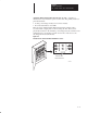
125 – 300 HP, 230VAC
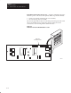
250 – 600 HP, 460VAC
4-12
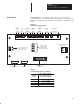
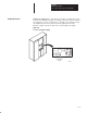
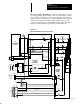
Field Pulse Transformer Boards (A5) – Figure 4.9 illustrates the major
hardware points on the board. The primary functions performed include:
• Isolate power bridge circuitry from control circuitry
• Provide dv/dt protection for SCRs
The board is physically mounted on the field power bridge buswork, with
the screw terminals used to mount the board also being used as the
connections to the incoming AC line and the DC bus.
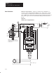
Figure 4.9
Field Pulse Transformer Board Hardware Location
AB0660A
Field Pulse
Transformer Board
R2
R8
T3
T1
G11 G12
C2
C3
J1
R3
R4
L3 L1
F1
F2
D10
G21 G22
T2
T4
R9
R1
MFG Revision No. Spare Parts Kit No.
1
AK