
Owner manual

Chapter 4
Hardware Description
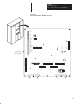
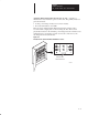
125 – 300 HP, 230VAC
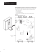
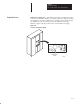
250 – 600 HP, 460VAC
4-10
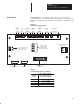
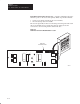
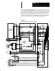
Main Control Board – Figure 4.7 illustrates the major hardware points on
the board. The board performs all control functions of the Bulletin 1395
drive. Hardware located on the board is used to support operation of the
microprocessor program. The primary functions performed include:
• Microbus interface
• Control firmware
• Analog signal interface
• Develop gate control signals sent to the Power Stage Interface.
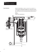
Figure 4.7
Main Control Board Hardware Location
J2 J4 J5
J10
J14
J6J7
J9
J8
Connection to Power Connection to
Connection To Power
Connection
Port A Port B
TP11
TP12
TP13
TP15
TP23
TP24
TP9 TP6
TP21
TP25
TP33
TP17 TP8 TP39
TP38 TP30
TP43
TP1
TP45
TP42
TP50
TP46
TP47 TP44
TP49
TP58
TP54
TP51
+5V –12V+12VDGND AGND
TP52 TP56TP55TP57
ISO+12V ISO+5VIGND
TP53 TP58
TP20
TP41
TP19
TP10
TP20
CP
VP
SP
TP34
TP27 TP26
TP31TP29
TP28
TP32
TP35
1
1
2
3
23
123
123
TP2 TP5
To
Encoder
Stage Interface Board Programming Terminal
Stage Interface Board
(To Adapter Board)(To Adapter Board)
J15
123
UMC8
Encoder
Voltage
Selection
5V 12V
J1
J12
1 2
34
J13
1 2
34
AB0667A
Main Control
Board