
Owner manual


Chapter 4
Hardware Description
125 – 300 HP, 230VAC
250 – 600 HP, 460VAC
4-2
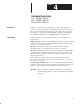
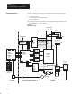
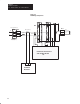
Hardware Overview Figure 4.1 provides an overview of the hardware components associated
with the 1395 drive. Hardware can be divided into one of three categories:
• Control Boards
• Control/Power Interface hardware
• Power Hardware
This chapter describes in general all of the major hardware components for
a 125 – 600HP (346 – 980A) drives.
Figure 4.1
Hardware Overview
Programming
Terminal
DHT/DMT
TB3
J4 J1
Main
Control
Board
A8
J5
J2
J7 J6
J8
J9
Unit
Power
Supply A6
J2
Power
Stage
Interface
A7
Feedback
Board
A1
A5
3 Phase AC
TB-8
J1
Arm P.T. &
Snubber A4
J1
Arm P.T. &
Snubber A3
J1
Arm P.T. &
Snubber A2
J1
J3
J4
J5
Field
Bridge
Feed
Back
Board
A1
J6 J2
J2
M1
A1
3 Phase
SCR
Bridge
Encoder
Armature
CT
CT
1 Phase AC
CONTROL
CONTROL/POWER INTERFACE
POWER
Fld P.T. &
Snubber
J2J7
TB-1
A2
CT
TB7
F
1
+
F
2
F
3
F
4
–
Field
F1
F2
F3
L1 L2 L3
1 2 3
Act 2
Act 1
Act 3
L1 L3
Wired By User
See Fig 4.4, 6.11
FCT
TB-5
See Fig 4.2
J2