
Owner manual

Chapter 3
Hardware Description
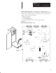
40 – 100 HP, 230VAC 75 – 200 HP, 460VAC
3-13
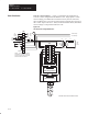
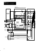
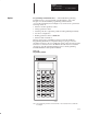
Figure 3.10
Field Pulse Transformer and Snubber Board Hardware Location
R1
R3
T1 T2
C1
G1 G2
Connection to SCRs
in PM7 of Field Bridge
L3 L1
F1
F2
G1 G2
Connection to SCRs
in PM8 of Field Bridge
R4
J1
Connection to Power Stage
Interface (SCR Gate Pulses)
MFG
Revision No.
Spare Part
Kit No.
C2
R5
T3 T4
D10
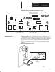
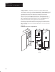
Peripheral Devices Unit Power Supply (A6) – The Unit Power Supply 115VAC input comes
from the user external 115VAC power supply. The AC voltage is rectified
and regulated to produce +5VDC and + 12VDC control voltages which are
distributed to the 1395 control boards through the Power Stage Interface.
Figure 3.11 shows the location of components on the Unit Power Supply.
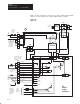
Figure 3.11
Unit Power Supply Hardware Location
AB0663B
Unit Power
Supply Board
C19
R30
F1
J1
C15 C16
C13
C8
C7
C11
C1
C6 C3
C9
J2