
Owner manual

Chapter 2
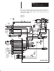
Hardware Description
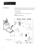
1 – 30 HP, 230VAC2 – 60 HP, 460VAC
2-14
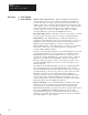
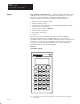
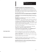
Options Programming Terminal Interface – The Programming Terminal (shown
in Figure 2.11) is used to access information in the firmware of the 1395.
Keypads on both the handheld programming terminal and the door
mounted terminal can be used to perform the following functions:
• Monitor real time parameter values
• Change parameter values
• Start/Stop the drive (depending on Model of Programming Terminal)
• Program drive configuration
• Save parameter values to EEPROM
• Monitor fault information
• Clear faults, system reset
• Autotune
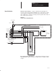
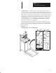
Interface between the 1395 Main Control Board and the handheld
Programming Terminal is accomplished using a 9 pin type connector
physically mounted on the end of TB3. The cable coming from the D-shell
connector is connected to J4 on the Main Control Board. For a detailed
description of the Programming Terminal, refer to the Programming
Terminal Installation and Operation Manual.
Figure 2.11
Programming Terminal
AB0446A
LOCAL
PROGRAMMING TERMINAL
START
JOG
1
JOG
2
STOP
ALT
LOCAL
DEC
REMOTE
INC
PRE 4
7
PRE 5
8
X REF
9
PRE 1
4
PRE 2
5
PRE 3
6
HOME
MENU
D
1
E
2
F
3
BASE
DEL
A
0
B
.
C
+/–
ENTER
Note: The Programming Terminal can be hand-held or door-mounted when used with the
mounting kit.