
Owner manual


Chapter 2
Hardware Description
1 – 30 HP, 230VAC 2 – 60 HP, 460VAC
2-8
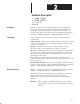
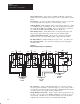
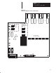
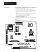
PSI/Switcher Board The primary function of the board (Figure 2.7) is to provide interface
between the Main Control Board, and the Power Board. The PSI/Switcher
board also provides the following:
• Distribution of DC logic power to the Main Control Board.
• Three-Phase line synchronization signals to the Main Control Board.
• Contactor and other logic control interface with the Main Control
Board.
• Rectification and Regulation of the external 115VAC power supply to
produce 5VDC and +/–12VDC control voltage.
• All current related feedback scaling circuitry.
• Customer basic interface for 115VAC.
• Field Current Range jumpers.
• Jumper selection for 24VDC or 115VAC for reset, motor thermal and
ECOAST.
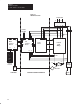
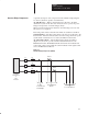
Figure 2.7
PSI/Switcher Board Hardware Location
F1
TB2
Customer Interface 115 VAC Control
TB1 FEEDBACK
BURDEN
J9
FAN1 FAN2
COM
PRM1PETE
115
RTN
115
PWR
115
CON
F3
J14
1 COM–IN
2 MOTOR TMP
3 RESET
4 E–COAST1
5 E–COAST2
6 COM–OUT
7 RDY/FLT1
8 RDY/FLT2
9 E–COAST+
10 E–COAST–
11 +24V
12 24VCOM
J10
J2
1 M1–AUX1
2 M1–AUX2
3 M1–COIL1
4 M1–COIL2
5 Chassis
F2
J4
HST2
J3
HST1
J13
J5
TB3 TRIP
BURDEN
T1
J11
MOTOR TEMP
ARMATURE ARMATURE
J12
115V24V
115V24V
RESET
J8
J7
J6
T2
C10
Q1
1 2 3 4 5 6 7
FCT–1
FCT–2
TD1–1
TD1–2
ACT1–1
ACT2–2
ACT1&2 RTN
1
2
3
4
4.5 – 10.6A
2.0 – 4.6A
0.5 – 2.1A
0.15 – 0.6A
J1
FIELD
CURRENT
SCALING
1 2 3
1 2 3
TP25
TP24
TP22 TP23 TP2 TP6 TP1 TP3 TP4 TP5
+5V COM +12V –12V +12VSO ICOM
TP17 TP19 TP18 TP15 TP12 TP10 TP9
TP20 TP14 TP16 TP13 TP11 TP8 TP7
5R 1R 6F FLD2 2R 4R 3F
3R 2F 4F FLD1 6R 5F 1F
1 2 3 4 5 6 7