
Owner manual

Chapter 8
Start–Up
8-11
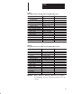
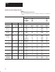
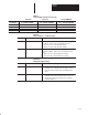
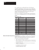
Table 8.J
Rated Fld Brdg I Settings (Parameter 616)
J1 Jumper
1
2
3
4
1 – 30 HP, 240VDC
2 – 60 HP, 500VDC
10.6
4.6
2.1
0.6
21.2
9.2
4.2
1.2
40 – 100 HP, 240VDC
75 – 200 HP, 500VDC
125 – 300 HP, 240VDC
250 – 600 HP, 500VDC
42.2
18.4
8.7
2.4
Series B Series A Series B MKVA
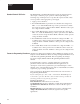
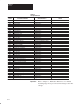
Table 8.K
Basic Parameters — Feedback Scaling
Parm
739
740
Parameter Name
K Arm Volts
K AC Volts
Numerical value used to scale the armature voltage
feedback. Values to be entered at this time are:
6414 = for 150 – 300 rated arm voltage
12321 = for 300 – 850 rated arm voltage
Description
Numerical value used to scale the incoming AC line
voltage feedback. Values to be entered at this time
are:
3872 = for 150 – 300 rated AC line voltage
7473 = for 300 – 690 rated AC line voltage
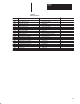
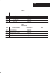
Table 8.K.A
Bridge Switch Delay Setting
Parm
744
Parameter Name
Bridge Switch Delay – Normal Applications (for armature time constants
in range of 1 to 100 mS) value should be set to 0.
Non–Zero Values will effect the bandwidth of the
drive.
Description
– High Inductance applications (Armature time
constants greater than 100mS) value needs to be
adjusted according to the parameter description
found in Chapter 7.