
User guide

Chapter 2
Hardware Description
2-7
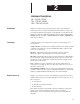
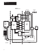
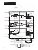
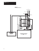
Control Boards Feedback Board – Figure 2.5 illustrates the major hardware points on the
board. The primary function of the board is to provide scaling and transfer
of feedback signals coming from power bridge devices being sent to the
Power Stage Interface and eventually to the Main Control Board.
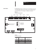
Figure 2.5
Feedback Board (A1) Overview
TB2
MFG Revision No.
Assembly Part No.
Connection for AC current
feedback burden resistor
(Factory Installed)
1 23
1
4
TB1
J2
TB3
56789 11 13 15 17 18 20 23
J1
3
2
4
24VDC
AC Current
Feedback from
ACT–1, 2,3
Field Current
Feedback from
FCT
3 Phase Incom-
ing AC Line
voltage Feed-
back
From Heatsink
Thermoswitch
S1
DC Armature Volt-
age Feedback
Connection to Power
Stage Interface
Jumper Selection
for Field Current
Feedback Scaling
(By User At Start–
Up)
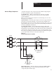
Table 2.A
Feedback Board Jumpers
J1
Jumper
Position
Standard Field
42.4A
18.5A
8.7A
2.4A
1
2
3
4
Optional Field
70.7A
30.7A
14.5A
4.0A