
Owner manual


Wiring Your External Shunt Resistor (Series C)
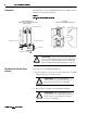
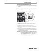
1. Locate and unplug the J11 connector on the bottom of the system
module.
2.
Remove and discard the jumper wire between J11-1 and J11-2, as
shown in Figure 4.
3. Install the shunt resistor wire leading to the fuse in connector
J11-1.
4. Install the other shunt resistor wire in connector J11-3.
5. Tighten the J11 connector screws (torque value = 0.56-0.62 N-m,
5.0-5.6 lb-in.).
6. Re-apply power and resume operation. Refer to the 1394 Digital,
AC, Multi-Axis Motion Control System User Manual (publication
1394-5.0) for startup information.
Important: Use fuse replacement kit (1394-SR10A-FUSE-A) when
replacing the 1394-SR10A shunt fuse. Refer to the 1394
Digital, AC, Multi-Axis Motion Control System User
Manual (publication 1394-5.0) for additional
information regarding fuse replacement kits.
1 2 3
J11
1394 bottom view
Remove jumper