394 SERCOS Interface Multi-Axis Motion Control System (Catalog Numbers 1394C-SJT05-D, 1394C-SJT10-D, 1394C-SJT22-D) Integration Manual
Important User Information Because of the variety of uses for the products described in this publication, those responsible for the application and use of this control equipment must satisfy themselves that all necessary steps have been taken to assure that each application and use meets all performance and safety requirements, including any applicable laws, regulations, codes and standards.
Table of Contents Preface Who Should Use this Manual . . . . . . . . . . . . . Purpose of this Manual . . . . . . . . . . . . . . . . . Contents of this Manual . . . . . . . . . . . . . . . . . Related Documentation . . . . . . . . . . . . . . . . . Conventions Used in this Manual . . . . . . . . . . Product Receiving and Storage Responsibility . Allen-Bradley Support . . . . . . . . . . . . . . . . . . Local Product Support . . . . . . . . . . . . . . . Technical Product Assistance . . . . . . . . . .
ii Table of Contents Supplemental Troubleshooting Information. . . . . . . . . . . Tools for Changing Parameters . . . . . . . . . . . . . . . . . Using Analog Test Points to Monitor System Variables Changing Default Digital Output Settings . . . . . . . . . . Replacing System and Axis Modules . . . . . . . . . . . . . . . . Before You Begin . . . . . . . . . . . . . . . . . . . . . . . . . . . Removing an Axis Module. . . . . . . . . . . . . . . . . . . . . Installing a Replacement Axis Module . . . . .
Preface Read this preface to familiarize yourself with the rest of the manual.
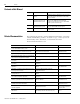
P-2 Preface Contents of this Manual Chapter Title Contents Preface Describes the purpose, background, and scope of this manual. Also specifies the audience for whom this manual is intended. 1 Commissioning Your 1394 SERCOS Interface System Provides steps to follow when configuring your 1394 with the Logix SERCOS interface module and describes how to apply power to your 1394 SERCOS interface system for the first time.
Preface Conventions Used in this Manual Product Receiving and Storage Responsibility P-3 The following conventions are used throughout this manual: • Bulleted lists such as this one provide information, not procedural steps. • Numbered lists provide sequential steps or hierarchical information. • Words that you type or select appear in bold. • When we refer you to another location, the section or chapter name appears in italics.
P-4 Preface Allen-Bradley Support Allen-Bradley offers support services worldwide, with over 75 Sales/ Support Offices, 512 authorized Distributors and 260 authorized Systems Integrators located throughout the United States alone, plus Allen-Bradley representatives in every major country in the world.
Chapter 1 Commissioning Your 1394 SERCOS Interface System Chapter Objectives This chapter provides you with the information to set up, configure, and apply power to your 1394 system.
1-2 Commissioning Your 1394 SERCOS Interface System General Startup Precautions The following precautions pertain to all of the procedures in this chapter. Be sure to read and thoroughly understand them before proceeding. ATTENTION ! ATTENTION ! Publication 1394-IN024B-EN-P — February 2004 This product contains stored energy devices. To avoid hazard of electrical shock, verify that all voltages on the system bus network have been discharged before attempting to service, repair or remove this unit.
Commissioning Your 1394 SERCOS Interface System Understanding 1394 Connectors 1-3 The following tables provide a brief description of the 1394 connectors.
1-4 Commissioning Your 1394 SERCOS Interface System Locating System Module Connectors and Indicators Use the figure below to locate the 1394C-SJT05-D and -SJT10-D System Module connectors and indicators. Figure 1.1 1394 System Modules (1394C-SJT05-D and -SJT10-D) System Module, front view (1394C-SJT05-D and -SJT10-D is shown) 1394 Digital Servo Controller SERCOS interfaceTM ! MORE THAN ONE DISCONNECT SWITCH MAY BE REQUIRED TO DE-ENERGIZE THE EQUIPMENT BEFORE SERVICE.
Commissioning Your 1394 SERCOS Interface System 1-5 Use the figure below to locate the 1394C-SJT22-D System Module connectors and indicators. Figure 1.
1-6 Commissioning Your 1394 SERCOS Interface System Locating Axis Module Connectors and Indicators Use the figure below to locate the axis module connectors and indicators. Shown below are typical 1394C-AM03, -AM04, and -AM07 axis modules. Although the physical size of the 1394C-AM50-xx and AM75-xx model is larger, the location of the connectors and indicators is identical. Figure 1.
Commissioning Your 1394 SERCOS Interface System Locating SERCOS Interface Fiber-Optic Connectors 1-7 Use the figure below to locate the SERCOS interface fiber-optic connectors. The fiber-optic ring is connected using the SERCOS Receive and Transmit connectors. Note: Plastic cable is available in lengths up to 32 m (105.0 ft). Glass cable is available in lengths up to 200 m (656.7 ft). Figure 1.
1-8 Commissioning Your 1394 SERCOS Interface System Configuring Your 1394 System Module To configure your 1394 system module: 1. Verify that there is no 360/480V AC input power or 24V logic power applied to the system and that the SERCOS fiber-optic cables are connected to the Tx and Rx connectors. To verify your fiber-optic cable connections, refer to the 1394 SERCOS Interface Installation Manual (publication 1394-IN002x-EN-P). 2.
Commissioning Your 1394 SERCOS Interface System 1-9 Refer to Figure 1.5 for an example of the fiber-optic ring connections between the 1394 system module(s) and the SoftLogix PCI card. Although Figure 1.5 only illustrates the SERCOS fiber-optic ring with the SoftLogix PCI card, node addressing for SoftLogix is done the same way as shown in the ControlLogix example. SoftLogix 1784-PM16SE SERCOS interface PCI Card 0 3456 72 ABCDE Figure 1.
1-10 Commissioning Your 1394 SERCOS Interface System 3. Set the baud rate using DIP switches 2 and 3. Refer to the table below for baud rate switch settings. Refer to figures 1.1 and 1.2 for DIP switch location. For this baud rate: Set switch 2: Set switch 3: 2M baud OFF OFF 4M baud OFF ON 8M baud ON OFF 4. Set the SERCOS optical power level to High using DIP switch 1, as shown in Figure 1.7. Refer to the table below for optical power level switch settings. Refer to Figure 1.
Commissioning Your 1394 SERCOS Interface System Configuring Your Logix SERCOS interface Module 1-11 This procedure assumes that you have finished wiring your 1394 SERCOS interface system and have finished configuring the 1394 system module switches. For greater detail on the RSLogix 5000 software as it applies to ControlLogix and SoftLogix modules, refer to the table below for the appropriate publication.
1-12 Commissioning Your 1394 SERCOS Interface System 5. Select the Date and Time tab. 6. Check the box Make this controller the Coordinated System Time master. IMPORTANT 7. Select OK. Publication 1394-IN024B-EN-P — February 2004 Only one ControlLogix processor can be assigned as the Coordinated System Time master.
Commissioning Your 1394 SERCOS Interface System 1-13 Configuring Your Logix Module To configure your Logix module: 1. Right-click on I/O Configuration in the explorer window and select New Module. The Select Module Type window opens. 2. Select 1756-MxxSE or 1784-PM16SE as appropriate for your actual hardware configuration. 3. Select OK. The Module Properties wizard opens. • Name the module • Select the slot where your module resides • Select an Electronic Keying option. 4.
1-14 Commissioning Your 1394 SERCOS Interface System 5. Select Data Rate, Cycle Time, and Optical Power settings. • Ensure the Data Rate setting matches DIP switches 2 and 3 (baud rate) as set on the system module, or use the Auto Detect setting. • Set the Cycle Time according to the table below. Logix SERCOS 1394 SERCOS interface Module System Module Series 1756-M08SE (Series A) C or D 1756-M08SE (Series B) D only Data Rate Mbit/s 4 8 SERCOS Ring Cycle Time ms Number of Axes 0.5 N/A 1.
Commissioning Your 1394 SERCOS Interface System 1-15 Configuring Your 1394 System Module To configure your 1394 system module: 1. Right-click on the new module you just created and select New Module. The Select Module Type window opens. 2. Select your 1394C-SJTxx-D system module. 3. Select OK. The Module Properties window opens. • Name the module • Set the Base Node address Note: Set node address in the software to match the node setting on the drive.
1-16 Commissioning Your 1394 SERCOS Interface System 9. Assign each axis to a node address (as shown in the window below). 10. Select Next until the following widow opens. 11. Select the Bus Regulator Catalog Number (shunt option) as appropriate for your actual hardware configuration.
Commissioning Your 1394 SERCOS Interface System 1-17 Configuring the Motion Group To configure the motion group: 1. Right-click Motion Groups in the explorer window and select New Motion Group. The New Tag window opens. 2. Name new motion group. 3. Select OK. New group appears under Motion Groups folder. 4. Right-click on the new motion group and select Properties. The Motion Group Properties window opens. 5. Select the Axis Assignment tab and move your axes (created earlier) from Unassigned to Assigned.
1-18 Commissioning Your 1394 SERCOS Interface System Configuring Axis Properties To configure axis properties: 1. Right-click on an axis in the explorer window and select Properties. The Axis Properties window opens. 2. Select the Drive/Motor tab. • Set the Amplifier (system module) Catalog Number • Set the Motor Catalog Number • Set Loop Configuration to Position Servo Note: For amplifier and motor catalog numbers refer to the amplifier and motor name plate. 3.
Commissioning Your 1394 SERCOS Interface System 1-19 6. Select the Fault Actions tab and click on the Set Custom Stop Action... tab. The Custom Stop Action Attributes window opens. • Set the Brake Engage Delay Time (refer to Brake Interconnect Diagrams in Appendix A for specific values). • Set the Brake Release Delay Time (refer to Brake Interconnect Diagrams in Appendix A for specific values). • Select Close. 7. Select OK. 8. Repeat steps 1-7 for each 1394 axis module. 9.
1-20 Commissioning Your 1394 SERCOS Interface System Applying Power to the 1394 SERCOS interface System This procedure assumes that you have wired your 1394 SERCOS interface system, your SERCOS interface module and verified the wiring. To apply power to your 1394 system: 1. Apply 24V logic power to the system module and verify that the logic power voltage at the input terminals of the system module is 24V AC (or 24V DC) ±10%. 2. Observe the status LED on the system module.
Commissioning Your 1394 SERCOS Interface System 1-21 5. Observe the status LEDs on the axis modules. If the axis module LED: Then: Alternates red and green Axis module ready. Go to step 7. Does not alternates red and green Go to the chapter Troubleshooting Your 1394 SERCOS Interface System. 6. Disconnect the load from the motor(s). ATTENTION ! To avoid personal injury or damage to equipment, disconnect the load from the motor(s).
1-22 Commissioning Your 1394 SERCOS Interface System 10. Observe the status LED on the system module. If the system module LED: Then: Is flashing green System module is ready. Go to step 11. Is not flashing green Go to the chapter Troubleshooting Your 1394 SERCOS Interface System. 11. Observe the status LED on the axis modules. Testing and Tuning Your Axes If the axis module LED: Then: Is flashing green Axis module is ready. Go to the section Testing and Tuning Your Axes.
Commissioning Your 1394 SERCOS Interface System 1-23 Testing Your Axes To test your axes: 1. Verify the load was removed from each axis. 2. Right-click on an axis in your Motion Group folder in the explorer window and select Axis Properties. The Axis Properties window appears. 3. Select the Hookup tab. 4. Select 2.0 as the number of revolutions for the test (or another number more appropriate for your application).
1-24 Commissioning Your 1394 SERCOS Interface System 5. Apply ENABLE input signal (Axis_x pin 1) for the axis you are testing. ATTENTION ! To avoid personal injury or damage to equipment, apply 24V ENABLE signal (Axis_x pin 1) only to the axis you are testing. 6. Select the Test (Marker/Feedback/Command & Feedback) button to verify connections. The Online Command window opens. Follow the on-screen test instructions.
Commissioning Your 1394 SERCOS Interface System 1-25 9. Select OK. If: Then: Your test completes successfully, this window 1. Select OK. appears: 2. Remove the ENABLE input signal (Axis_x pin 1) applied earlier. 3. Go to Tuning Your Axes. 1. Select OK. Your test failed, this widow appears: 2. Verify that the main three-phase bus power is up. 3. Verify that the ENABLE input signal (Axis_x pin 1) is applied to the axis you are testing. 4. Verify conversion constant entered in the Conversion tab. 5.
1-26 Commissioning Your 1394 SERCOS Interface System Tuning Your Axes To tune your axes: 1. Verify the load is still removed from the axis being tuned. ATTENTION ! To reduce the possibility of unpredictable motor response, tune your motor with the load removed first, then re-attach the load and perform the tuning procedure again to provide an accurate operational response. 2. Select the Tune tab. 3. Enter values for Travel Limit and Speed. In this example, Travel Limit = 5 and Speed = 2.
Commissioning Your 1394 SERCOS Interface System 1-27 6. Select the Start Tuning button to auto-tune your axis. The Online Command - Tune Servo window appears. When the test completes, the Command Status changes from Executing to Command Complete. 7. Select OK. The Tune Bandwidth window opens. Note: Actual bandwidth values (Hz) depend on your application and may require adjustment once motor and load are connected. Record your bandwidth data for future reference. 8. Select OK. 9.
1-28 Commissioning Your 1394 SERCOS Interface System 10. Select OK. If: Then: Your test completes successfully, this window appears: 1. Select OK. 2. Remove the ENABLE input signal (Axis_x pin 1) applied earlier. 3. Go to step 11. Your test failed, this widow appears: 1. Select OK. 2. Make an adjustment to motor velocity. 3. Refer to appropriate Logix motion module setup and configuration manual for more information. 4. Return to step 6 and run the test again. 11.
Chapter 2 Troubleshooting Your 1394 SERCOS Interface System Chapter Objectives 1 This chapter covers: • Safety Precautions • Understanding How to Detect a Problem • Troubleshooting System and Axis Module LEDs • Troubleshooting the SERCOS Network Status LED • Troubleshooting General System Problems • Troubleshooting System and Axis Module Faults • Troubleshooting General System Problems • Understanding Logix/Drive Fault Behavior • Supplemental Troubleshooting Information • Replacing Sy
2-2 Troubleshooting Your 1394 SERCOS Interface System Safety Precautions Observe the following safety precautions when troubleshooting your 1394 SERCOS interface system. ATTENTION ! DC bus capacitors may retain hazardous voltages after input power has been removed, but will normally discharge in several seconds. Before working on the drive, measure the DC bus voltage to verify it has reached a safe level or wait the full time interval listed on the warning on the front of the drive.
Troubleshooting Your 1394 SERCOS Interface System Troubleshooting System and Axis Module LEDs 2-3 The system module Status LED is visible from the front of the module. Refer to figures 1.1 and 1.2 for the location of the system module status LED. If the System Module LED is: Steady red Flashing red Alternating red and green Steady green Flashing green Not illuminated Potential Cause is: Possible Resolution is: Terminator not installed. • Install terminator. • • • • • Verify wiring.
2-4 Troubleshooting Your 1394 SERCOS Interface System The axis module status LED is visible from the front of the module. Refer to Figure 1.3 for the location of the axis module status LED. If the Axis Module LED is: Potential Cause is: Possible Resolution is: Malfunctioning axis module. • Verify wiring. • Verify that the slider and terminator connections are secure. • Secure wiring connections. • Replace the module. Flashing red Axis fault has occurred. • Verify wiring.
Troubleshooting Your 1394 SERCOS Interface System Troubleshooting the SERCOS Network Status LED 2-5 The SERCOS Network Status LED is located on the system module control board and visible with the system module door open. Refer to figures 1.1 and 1.2 for the location of the SERCOS Network Status LED. If the SERCOS Network Status LED is: Status is: Potential Cause is: Possible Resolution is: Steady Green Communication ready No faults or failures. System is ready. Control board failure.
2-6 Troubleshooting Your 1394 SERCOS Interface System Troubleshooting System and Axis Module Faults Fault messages are transmitted to the SERCOS controller through the SERCOS ring and/or SCANport. The tables on the following pages provide a description of system and axis module faults, the potential cause, and possible resolutions. Note: Fault messages are shown as seen in RSLogix software (bold) and when using the HIM or DriveExplorer (not bold).
Troubleshooting Your 1394 SERCOS Interface System Fault Message RSLogix (HIM): DriveHardFault (Contactor Fault) MotFeedbackFault (Fdbk Watch Dog) GroundShortFault (Ground Short) DriveHardFault (IDMA Load) Description: Three-phase power is either detected when it shouldn’t be or not detected when it should be. A feedback hardware or software fault detected. Excessive ground current in the system module was detected. Motor feedback hardware initialization fault detected.
2-8 Troubleshooting Your 1394 SERCOS Interface System Fault Message RSLogix (HIM): Description: SERCOSFault (SERCOS Same Addr) Duplicate node address detected on SERCOS ring. Verify that each SERCOS drive is assigned a unique node address. Shunt resistor continuous rating exceeded. The regenerative energy produced by the motor exceeded the limit of the shunt resistor. • Use a properly sized shunt or modify duty cycle of the application.
Troubleshooting Your 1394 SERCOS Interface System 2-9 Axis Module Faults Use the table below for troubleshooting axis module faults. Fault Message RSLogix (HIM): No Fault Message (condition indicated by on-screen message) Description: Potential Cause is: Possible Resolution is: Auto tune procedure failed to complete successfully. Motor or feedback device malfunction. • Check motor power/feedback wiring. • Refer to on-screen message for resolution. Hookup procedure failed to complete successfully.
2-10 Troubleshooting Your 1394 SERCOS Interface System Fault Message RSLogix (HIM): PositionErrorFault (Ax: Follow Error) DriveOvercurrent Fault (Ax: I(t) Fault) PosSoftOvertravel Fault (Ax: +Soft Ovrtrvl) NegSoftOvertravel Fault (Ax: -Soft Ovrtrvl) PosHardOvertravel Fault Description: Potential Cause is: Possible Resolution is: Axis position error limit has been exceeded. This fault can be configured for status only. The motor cannot keep up with the position command.
Troubleshooting Your 1394 SERCOS Interface System Fault Message RSLogix (HIM): MotFeedback NoiseFault Description: Potential Cause is: Possible Resolution is: Excessive noise detected on feedback signals. Poor grounding. • Check ground clamp connectors. • Check system module grounding. The motor thermal switch was tripped. Motor overload. • Allow motor to cool down and investigate the cause of the motor overload. • Motor not sized properly. Motor velocity exceeded the overspeed trip limit.
2-12 Troubleshooting Your 1394 SERCOS Interface System Troubleshooting General System Problems Condition: Axis or System runs uncontrollably Axis or System is unstable You cannot obtain the motor acceleration/deceleration that you want Motor does not respond to a Velocity Command Use the tables below for troubleshooting general system faults. Potential Cause is: Possible Resolution is: The position feedback device is incorrect or open. Check wiring. Unintentionally in torque mode.
Troubleshooting Your 1394 SERCOS Interface System Condition: Presence of noise on Command or resolver signal wires No Rotation Overheating Abnormal Noise Erratic Operation - Motor locks into position, runs without control or with reduced torque 2-13 Potential Cause is: Possible Resolution is: Recommended grounding per installation instructions and Appendix A has not been followed. • Verify grounding. • Route wire away from noise sources. External 50/60 Hz line frequency may be present.
2-14 Troubleshooting Your 1394 SERCOS Interface System Understanding Logix/Drive Fault Behavior This section provides the drive fault actions and indicates whether the fault action is programmable. The following drive fault action definitions apply: Drive Fault Action Definition Shutdown The drive disables and the contactor enable relay opens. Uncontrolled stop, motor coasts to a stop. Disable Drive The drive is disabled. Uncontrolled Stop, motor coasts to a stop.
Troubleshooting Your 1394 SERCOS Interface System Fault Message RSLogix (HIM): DriveHardFault (Memory Init) DriveHardFault (NV Mem Init) DriveHardFault (Objects Init) PowerPhaseLoss Fault 2 2-15 Description: Drive Fault Action RSLogix Programmable Fault Action? Memory hardware initialization fault detected. SHUTDOWN No Non-volatile memory is corrupt. SHUTDOWN No Non-volatile memory is corrupt.
2-16 Troubleshooting Your 1394 SERCOS Interface System Axis Module Faults Fault Message RSLogix (HIM): Description: Drive Fault Action RSLogix Programmable Fault Action? No Fault Message (condition indicated by on-screen message) Auto tune procedure failed to complete successfully. DISABLE No Hookup procedure failed to complete successfully. DISABLE No Active when serial ring detects unknown axis module. SHUTDOWN No Auxiliary encoder has encountered an illegal state transition.
Troubleshooting Your 1394 SERCOS Interface System Fault Message RSLogix (HIM): HardOvertravel Fault 2-17 Description: Drive Fault Action RSLogix Programmable Fault Action? Axis moved beyond the physical travel limits in the positive/negative direction. This fault can be configured for status only. STOP Yes Motor encoder has encountered an illegal state transition. DISABLE No Communication was not established with an intelligent (i.e. Stegmann) encoder.
2-18 Troubleshooting Your 1394 SERCOS Interface System Supplemental Troubleshooting Information This section provides information for accessing and changing parameters not accessible through RSLogix 5000 software. Tools for Changing Parameters Most parameters are accessible through RSLogix 5000 software. Alternatives to RSLogix 5000 software for changing parameters include the Human Interface Module (HIM) and DriveExplorer software. Refer to the table below for catalog numbers.
Troubleshooting Your 1394 SERCOS Interface System 2-19 Changing Parameters Using the HIM To navigate using the HIM, refer to the programming flowchart in the figure below. Figure 2.
2-20 Troubleshooting Your 1394 SERCOS Interface System Using Analog Test Points to Monitor System Variables There are four analog output test points accessible from the connector on the front of the system module (refer to the figure below for the connector location). Figure 2.3 Analog and Relay Output Connectors 1394C-SJTxx-D (5 and 10 kW) 1394 Digital Servo Controller SERCOS interfaceTM ! MORE THAN ONE DISCONNECT SWITCH MAY BE REQUIRED TO DE-ENERGIZE THE EQUIPMENT BEFORE SERVICE.
Troubleshooting Your 1394 SERCOS Interface System 2-21 To use the four analog output test points to monitor system variables, refer to the table below. Analog Output: Controlling Parameter Number: Default Parameter Number: Scale Parameter: 1 681 40 682 2 683 1040 684 3 685 2040 686 4 687 3040 688 The value entered in Scale Parameter will scale the analog output so that you can get a full scale reading of the specific parameter for the dynamic range or values you are testing.
2-22 Troubleshooting Your 1394 SERCOS Interface System Changing Default Digital Output Settings Change the system module parameters listed below by using either the HIM or DriveExplorer software. To locate the relay output connector, refer to Figure 2.3.
Troubleshooting Your 1394 SERCOS Interface System Replacing System and Axis Modules 2-23 Use these procedures to: • Determine what you need to replace modules • Remove an axis module • Install a replacement axis module • Remove a system module • Install a replacement system module Note: If you are replacing the fuse in 1394-SRxxxx shunt modules refer to 1394 Shunt Modules Fuse Replacement Kit Installation Instructions (publication 1394-6.6).
2-24 Troubleshooting Your 1394 SERCOS Interface System Removing an Axis Module To remove an axis module: 1. Remove 24V control power and main input power from the system. ATTENTION ! To avoid shock hazard or personal injury, assure that all power has been removed before proceeding. This system may have multiple sources of power. More than one disconnect switch may be required to de-energize the system. 2. Allow five minutes for the DC bus to completely discharge before proceeding.
Troubleshooting Your 1394 SERCOS Interface System 2-25 Installing a Replacement Axis Module To install a replacement axis module: 1. Install the top mounting fastener on the system panel for the axis module. The head of the fastener should be at least 6.35 mm (0.25 in.) from the panel. Refer to the 1394 SERCOS Interface Installation Manual (publication 1394-IN002x-EN-P) for more information. 2. If you are mounting: Do this: A 1394x-AM03, -AM04, -AM07 -AM50-IH, or -AM75-IH axis module Go to main step 3.
2-26 Troubleshooting Your 1394 SERCOS Interface System 10. Apply power to the system. 11. Verify that the system is operating properly. Note: Because system and axis parameters reside in the system module software, you do not need to perform any tuning or setup at this time. Removing a System Module To remove a system module: 1. Remove the main input power from the system. ATTENTION ! To avoid shock hazard or personal injury, assure that all power has been removed before proceeding.
Troubleshooting Your 1394 SERCOS Interface System 2-27 8. Disconnect the slide-and-lock mechanism on the system module. 9. Open the system module door. 10. Label and remove any feedback and/or communication connectors from the control board. 11. Loosen the top and bottom fasteners that hold the module in place. 12. Lift the module up and pull it out. Installing a Replacement System Module To install a replacement system module: 1.
2-28 Troubleshooting Your 1394 SERCOS Interface System 11. Apply main input power to the system module. IMPORTANT If you are replacing a Series C system module with a Series D system module, you must auto tune each axis to ensure proper operation. Refer to Testing and Tuning Your Axes beginning on 1-22 for more information. 12. Verify that your system is operating properly.
Appendix A Interconnect Diagrams Chapter Objectives 1 This appendix covers the following: • Power Interconnect Diagrams • Shunt Module Interconnect Diagrams • Axis Module/Motor Interconnect Diagrams • Understanding Motor Thermal Switches • Brake Interconnect Diagrams Publication 1394-IN024B-EN-P — February 2004
A-2 Interconnect Diagrams 1394 SERCOS Interface Interconnect Diagram Notes This section provides interconnect diagrams to assist you in wiring the 1394 system. The notes in the table below apply to the interconnect diagrams on the pages that follow. Note: Information: 1 For power wiring specifications, refer to the 1394 SERCOS Interface Installation Manual (publication 1394-IN002x-EN-P).
Interconnect Diagrams Power Interconnect Diagrams A-3 The power interconnect wiring for the 1394 SERCOS interface system module is shown in the figures below. Figure A.1 1394C-SJT05-D or -SJT10-D Interconnect Diagram 1394 SERCOS interface SYSTEM MODULE 1394C-SJT05-D or -SJT10-D DC MINUS BUS J4 J5 LOGIC POWER & SIGNALS J6 Notes 4, 9 DC BUS POS. Note 7 STOP* 24V ac/dc or 120V ac 50/60 Hz DC BUS NEG.
A-4 Interconnect Diagrams Shunt Module Interconnect Diagrams In the figure below, the 1394 system module is shown wired for internal shunt operation. This is the factory default jumper setting. IMPORTANT Internal shunt operation is only present on the 1394 system modules listed in Figure A.3. Figure A.
Interconnect Diagrams A-5 In the figure below, the 1394C-SJT22-D system module is show wired with an external shunt resistor. IMPORTANT All 1394 configurations with 22 kW system modules require an external shunt module. Figure A.
A-6 Interconnect Diagrams Axis Module/Motor Interconnect Diagrams This section contains the motor power, brake, and feedback signal interconnect diagrams between an Axis Module and MP-Series, 1326AB, and 1326AS servo motors. In the figure below, the 1394 axis module is shown connected to MPSeries Low Inertia (460V) motors. Figure A.6 Axis Module to MP-Series Low Inertia Motors Interconnect Diagram TERMINATOR CONNECTED TO LAST AXIS MODULE 1394 AXIS MODULE 1394C-AMxx-xx LOGIC POWER & SIGNALS DC BUS POS.
Interconnect Diagrams A-7 In the figure below, the 1394 axis module is shown connected to 1326AB (460V) servo motors. Figure A.7 Axis Module to 1326AB Motors Interconnect Diagram TERMINATOR CONNECTED TO LAST AXIS MODULE 1394 AXIS MODULE 1394C-AMxx-xx Thermostat and Brake Noise Filtering Note 12 LOGIC POWER & SIGNALS Motor Thermal Switch Filter (Series C) Motor Brake Filter (Series C) TB1 DC BUS POS. DC BUS NEG.
A-8 Interconnect Diagrams In the figure below, the 1394 axis module is shown connected to 1326AS (460V) servo motors. Figure A.8 Axis Module to 1326AS Motors Interconnect Diagram TERMINATOR CONNECTED TO LAST AXIS MODULE 1394 AXIS MODULE 1394C-AMxx-xx Thermostat and Brake Noise Filtering Note 12 LOGIC POWER & SIGNALS Motor Thermal Switch Filter (Series C) Motor Brake Filter (Series C) TB1 DC BUS POS. DC BUS NEG.
Interconnect Diagrams Thermal Switch and Brake Interconnect Diagrams A-9 This section provides thermal switch and brake interconnect diagrams. Understanding Motor Thermal Switches Thermal switches, internal to each servo motor, can be wired in series to protect the motor from overheating. In the event of a fault condition, the switch opens and the motor responds to the system configuration. The explanation and example diagrams that follow show how to wire motor thermal switches to your system module.
A-10 Interconnect Diagrams Figure A.
Interconnect Diagrams A-11 The example below shows 1394 (Series C) axis modules wired for thermal fault monitoring. Depending on how the 1394 system is configured, the fault can be used to disable one or all of the four axis modules. Figure A.
A-12 Interconnect Diagrams The example below shows 1394 (Series A and B) axis modules (no internal brake or thermal switch filter). Separate 24V dc isolation power supply and relay (CR2) are recommended. Using this start/stop string configuration all axes are disabled when any one motor faults. Figure A.
Interconnect Diagrams A-13 The example below shows 1394 (Series A and B) axis modules wired for thermal fault monitoring. Depending on how the 1394 system is configured, the fault can be used to disable one or all of the four axis modules. Two separate 24V dc power supplies and four relays (CR2CR5) are included to isolate the thermal inputs from conducted noise. Figure A.
A-14 Interconnect Diagrams Brake Interconnect Diagrams The relay outputs (Output 0-3) are linked to the Brake Enable/Disable configuration in RSLogix 5000 axis properties to allow control of a motor brake for each axis. When an axis is enabled, the configured output relay contact will close to disengage the associated motor brake. At the same time, the axis will command sufficient torque to hold the motor's position while the brake is disengaging.
Interconnect Diagrams A-15 The example below shows 1394 series C axis modules with internal brake filtering. Each axis is connected to a motor with a brake rated at less than 1A. A separate pilot relay is not required. Motor brakes that do not require a pilot relay are shown in the table below. Note: Suppression devices and pilot relays impact motor brake response time.
A-16 Interconnect Diagrams The example below also shows 1394 series C axis modules with internal brake filtering. Each axis is connected to a motor with a brake rated at greater than 1A. A separate pilot relay is required for brake current handling. Note: Suppression devices and pilot relays impact motor brake response time.
Interconnect Diagrams A-17 The example below shows 1394 Series B axis modules without internal brake filtering. Any axis connected to a motor with a brake requires a separate pilot relay for noise isolation. Figure A.
A-18 Interconnect Diagrams Publication 1394-IN024B-EN-P — February 2004
Index Numerics 1326AB (M2L/S2L) interconnect diagram A-7 1326AS interconnect diagram A-8 1394 SERCOS commissioning 1-1 configuring 1-7 1394 system troubleshooting 2-1 1756-MxxSE P-1 1756-MxxSE interface module 1-7 1784-PM16SE P-1 1784-PM16SE PCI card 1-7 A analog connector 2-20 analog test points 2-20 applying power 24V 1-20 360/480V 1-21 attribute tab 1-17 axis assignment tab 1-17 axis module connector designators 1-3, 1-6 installing replacement 2-25 removing 2-24 status LED 2-4 axis module status LED 1-
I-2 Index axis unknown 2-9 Bus Loss 2-9 desat 2-9 drive enable 2-9 Follow Error 2-10 -hard ovrtrvl 2-10 I(t) Fault 2-10 Motor Overtemp 2-11 Mtr Fdbk AQB 2-10 Mtr Fdbk comm 2-9, 2-10 Mtr Fdbk Loss 2-10 Mtr Fdbk Noise 2-11 Overspeed 2-11 Overtemp 2-11 Power Fault 2-11 -soft ovrtrvl 2-10 axis module (Logix) AuxFeedback 2-9 AuxFeedbackNoise 2-9 DriveEnableInput 2-9 DriveHard 2-9 DriveOvercurrent 2-9, 2-10, 2-11 DriveOvertemp 2-11 DriveUndervoltage 2-9 MotFeedback 2-10 MotFeedbackNoise 2-11 MotorOvertemp 2-11
Index L LED axis module status 1-21, 1-22, 2-4 network status 1-20, 2-5 SERCOS module 1-20 system module status 1-20, 1-22, 2-3 local support P-4 Logix connector designators 1-7 Logix interface module 1-11 loop configuration 1-18 M manuals on-line P-4 modules installing replacement axis I-3 P parameters, changing 2-18 power control 24V 1-20 input 1-21 interconnect diagrams A-3 precautions general startup 1-2 safety 2-2 problem report form P-4 R receiving and storage P-3 related documentation Motion B
I-4 Index System Design for Control of Electrical Noise Reference Manual P-2 system module connector designators 1-3 connector locations 1-4, 1-5 installing a replacement 2-27 removing 2-26 system module status LED 1-20, 1-22, 2-3 shutdown 2-14 status only 2-14 stop motion 2-14 supplemental troubleshooting information 2-18 changing digital output settings 2-22 changing parameters 2-18 using analog test points 2-20 T technical product assistance P-4 testing axes hookup tab 1-23 testing motors 1-22 tro
For more information refer to our web site: www.ab.com/motion For Rockwell Automation Technical Support information refer to: www.rockwellautomation.com/support or Tel: (1) 440.646.3434 Publication 1394-IN024B-EN-P — February 2004 Supersedes Publication 1394-IN024A-EN-P — July 2001 Copyright © 2004 Rockwell Automation. All rights reserved. Printed in USA.