
Installing Your Drive Interface Module Owner's manual

Publication 1394-5.12 — December 1999
Installation Instructions
Installing Your 1394 Drive Interface
Module
(Catalog Number 1394-DIM)
Introduction
This publication provides installation instructions for adding the 1394
Drive Interface Module to your 1394 system.
Use these instructions
in conjunction with the
1394 Digital, AC, Multi-Axis Motion Control
System User Manual
(publication 1394-5.0).
Note: For instructions on using GML Commander to configure your
1394-DIM, refer to the
GML Commander Reference Manual
(publication GMLC-5.2).
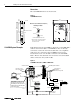
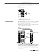
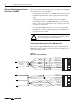
The 1394-DIM acts as an interface between one 1394 GMC/GMC
Turbo system module and an external axis drive(s).
On the 1394
x
-SJT
xx
-C, -C-RL, -T, and -T-RL, the 1394-DIM acts in
place of one to four axis modules. On the 1394C-SJT
xx
-L and -L-RL
the 1394-DIM acts in place of one axis module. The 1394-DIM
passes a standard servo output signal from the system module to each
external drive connected to the 1394-DIM. Using a 1394-DIM as part
of a 1394 system lets you control external drives and motors of any
size.
Specifications
The table below lists the 1394-DIM specifications.
Certification
The certified 1394-DIM product displays the following:
• UL Listed (File E59272)
• CUL Listed
• CE marked for all applicable directives
The: For the 1394-DIM is:
Firmware version 3.7 or higher with 1394x-SJTxx-C-xx and -T-xx systems
3.9 or higher with 1394C-SJTxx-L-xx systems
Software GML Commander, version 4.01 or higher
Input voltage 24V, 50 kHz provided by the 1394x-SJT-xx system module
Analog output information (Px-1,2)
Voltage 0 to ± 10V analog
Signal isolation 1500V rms
Resolution 12 bits, 4.88 mV
Impedance 220 ohms
Offset ± 80 mV maximum, compensated to 0 through software
setup
Drive OK 15V DC @ 5 mA supplied by the DIM
Drive enable output 30V DC @ 1 A
Operating temperature 0
°
to 50
°
C (32
°
to 122
°
F)
Relative humidity 5-95%
Weight 3 kg (6.6 lb)