
Owner's manual


Troubleshooting
Chapter 10
10-67
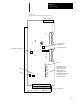
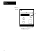
Figure 10.1
Logic Control Board Test Point Locations
DS1
DS2
DS3
DS4
DS5
DS6
DS7
DS8
TB1
120
110
Current Feedback
Scaling Switch
Configuration Switch
Offset
Overtemperature (red)
Power Factor (red)
Control Power (red)
Overvoltage (red)
Undervoltage (yellow)
Current Foldback (yellow)
Run Enable (green)
Drive Ready (green)
Gain
Scale
TB2
Adjustable Current Limit
R144
R148
R132
S2
S1
ON
OFF
112
Resolver Signals
TP11
TP2
TP3
TP6
TP13
TP12
TP14
TP21
TP22
R1
TP16 TP14
TP11
TP13 TP7
TP12
TP29 TP15
TP30
Bottom Logic Board