
Owner's manual

Inputs, Outputs and Adjustments
Chapter 5
5-30
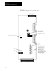
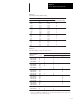
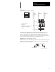
Figure 5.2
Terminal Block, Potentiometer and Switch Locations
DS1
DS2
DS3
DS4
DS5
DS6
DS7
DS8
TB1
120
110
Current Feedback
Scaling Switch
Configuration Switch
Offset
Overtemperature (red)
Power Factor (red)
Control Power (red)
Overvoltage (red)
Undervoltage (yellow)
Current Foldback (yellow)
Run Enable (green)
Drive Ready (green)
Gain
Scale
TB2
R144
R132
S2
S1
ON
OFF
112
I/O Signals
Resolver Signals
Adjustable Current Limit
R148
R1