Table of Contents 1391B-ES Instruction Manual Introduction Chapter 1 Manual Objectives . . . . . . . . . . . . . . . . . . . . . . . . . . . . . . . . . . . . . . . . . 1391 Series D . . . . . . . . . . . . . . . . . . . . . . . . . . . . . . . . . . . . . . . . . . . . . General Precautions . . . . . . . . . . . . . . . . . . . . . . . . . . . . . . . . . . . . . . . . Controller Description . . . . . . . . . . . . . . . . . . . . . . . . . . . . . . . . . . . . . . Standard Features . . . . . . . . . .
Table of Contents 1391B-ES Instruction Manual Inputs, Outputs and Adjustments Chapter 5 Chapter Objectives . . . . . . . . . . . . . . . . . . . . . . . . . . . . . . . . . . . . . . . . . Inputs/Outputs . . . . . . . . . . . . . . . . . . . . . . . . . . . . . . . . . . . . . . . . . . . . Potentiometer Adjustments . . . . . . . . . . . . . . . . . . . . . . . . . . . . . . . . . . Switch Settings . . . . . . . . . . . . . . . . . . . . . . . . . . . . . . . . . . . . . . . . . . .
Chapter 1 Introduction Manual Objectives This manual is meant to guide the interface, installation, setup and troubleshooting of a 1391B-ES AC Servo Controller. The contents are arranged in order from a general description of the controller to troubleshooting and maintenance. To ensure successful installation and operation, the material presented must be thoroughly read and understood before proceeding. Particular attention must be directed to the Attention and Important statements contained within.
Chapter 1 Introduction General Precautions In addition to the precautions listed throughout this manual, the following statements which are general to the controller must be read and understood. ! ! ! ATTENTION: Only personnel familiar with the 1391B-ES Servo Controller and associated machinery should plan or implement the installation, start-up and subsequent maintenance of the controller. Failure to comply may result in personal injury and/or equipment damage.
Chapter 1 Introduction The 1391B-ES is generally used with a computer aided, closed loop positioning system to control the position and linear or rotary motion of various machine members on an automated machine. All components are mounted in an open framed package with a slide-on front cover. The controller is intended to be panel mounted in an enclosure and ventilated with filtered and/or cooled air. An internal fan is included to circulate air over the power heat sink.
Chapter 1 Introduction Options/Modifications The 1391B-ES contains most functions needed in a servo system. The following are selectable at the user’s option: - Contactor Auxiliary Switch Two N.O. contacts are mounted on the main power contactor and wired to the power terminal block. These contacts can be used in a motor brake control circuit or as an indicator that the contactor has closed.
Chapter 1 Introduction Figure 1.
Chapter 1 Introduction End of Chapter 1-6
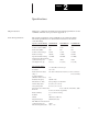
Chapter 2 Specifications Chapter Objectives Chapter two contains the electrical and environmental specifications for the 1391B-ES. Dimensions are provided in Appendix A. Controller Specifications The general specifications of the 1391B-ES are provided in the listing below. The specifications are divided when necessary for the various controller ratings.
Chapter 2 Specifications Specifications are for reference only and are subject to change without notice. Environmental Specifications The 1391B-ES must be mounted in an enclosure that is clean, dry and ventilated by filtered or cooled air. Enclosures vented with ambient air must have appropriate filtering to protect against contamination caused by oils, coolants, dust, condensation etc.
Important: Power Dissipation figures shown are for use in calculating cumulative system heat dissipation to ensure ambient temperature inside enclosure does not exceed 60° C (140° F).
Chapter 3 Receiving, Unpacking and Inspection Chapter Objectives Chapter 3 provides the information needed to unpack, properly inspect and if necessary, store the 1391B-ES and related equipment. The section entitled Inspection provides a complete explanation of the 1391B-ES catalog numbering system. Receiving It is the responsibility of the user to thoroughly inspect the equipment before accepting the shipment from the freight company. Check the item(s) received against the purchase order.
Chapter 3 Receiving, Unpacking and Inspection Isolation Transformer 1391 – First Position Bulletin Number T 015 Second Position Third Position T Fourth Position Description Transformer Open Core and Coil Number 015 035 050 100 125 150 T Primary Voltage & Frequency Fifth Position Secondary Voltage kVA Letter Description Letter Description 1.5 3.5 5.0 10.0 12.5 15.
Chapter 3 Receiving, Unpacking and Inspection Bulletin 1391B-ES Controller 1391B – First Position ES A A Third Position Type and Construction Fourth Position Bulletin Number Second Position Speed Capability Code Description Letter Description B Blan Standard k 1391B Letter Standard ES Extended Speed Range A Description Open Frame, Internal Heat Sink 45 – xxx Sixth Position Nominal Output Voltage Fifth Position Current Rating Letter Number Description Description 15A RMS Cont.
Chapter 3 Receiving, Unpacking and Inspection 1326AB Servomotor 1326 A B First Position Second Position Bulletin Type Number Letter A Description AC Servomotor PM Type – Third Position Design Description Factory use only A 3 E Description Description Sequentially lettered to designate frame diameters. Sequentially numbered to indicate stack length within a given frame size. Letter RPM C Code 600 Description A4 5.88” (149 mm) A7 0 A5 7.
Chapter 3 Receiving, Unpacking and Inspection Motor Junction Box Kit3 1326A – MO B D First Position Bulletin Number – RJA B Second Position Third Position Type Description Code Description Code Description MO D Modification Kit RJA B For all AB-A and AB-B Series Motors For all AB-B4 and AB-Cx Series Motors RJB C 3 The motor comes standard with IP65 plug style connectors mounted radially to the motor.
Chapter 3 Receiving, Unpacking and Inspection Feedback Coupling 1326 – First Position MO D – Second Position Bulletin Number C1 Third Position Coupling Size Type Code Description Code Size – Motor Shaft to Encoder Shaft MO D Modification Kit C1 C2 3/8” to 3/8” (9.5 mm to 9.5 mm) 3/8” to 1/4” (9.5 mm to 6.
Chapter 3 Receiving, Unpacking and Inspection Power and Feedback Cables 1326 – C First Position Second Position Bulletin Type Number P T Fifth Position Sixth Position Function Power Track Cable Motor Size Used On Cable Length Letter Description Letter Description Letter Description Code Type Code Description C P T All Series K Blan k Standard Cable AB Series A & B (except C 1326AB-B4) 15 Connector Kit (No Cable) 30 15’ (4.6m) 50 30’ (9.1m) 100 50’ (15.
Chapter 3 Receiving, Unpacking and Inspection End of Chapter 3-17
4 Chapter Description of Operation Chapter Objectives Chapter 4 is intended to familiarize the reader with the circuitry of the 1391B-ES in terms of function and operation. General The 1391B-ES PWM Servo Controller is made up of the following: 300V DC power supply, power transistor output modules, shunt regulator circuit, logic power supply, Logic Control Boards, isolated current sensing, circuit breaker and line contactor.
Chapter 4 Description of Operation The three-phase relationship between the reference signal and the timing wave provide a PWM wave to the power transistor base drive. This base drive switches the power transistors across the 300V DC bus, providing current to the motor windings, thus causing the motor to turn. A resolver attached to the motor provides a signal corresponding to the actual rotor position of the motor.
Chapter 4 Description of Operation The shunt regulator behavior is further modified by an adjustable duty cycle timer. The timer is used to model the shunt resistor temperature. SW1, a selector switch located on the top of the controller (see Figure 1.1) determines the temperature level and therefore the average power level at which the controller will trip out. When this level is reached, the controller will be forced to trip out on an Overvoltage Fault.
Chapter 4 Description of Operation Fault Monitoring and Detection A number of Fault Monitor and Detection functions exist on the 1391B-ES that guard the controller and help to minimize motor and system faults. The occurrence of a fault will cause the controller to trip out. In this condition, the Drive OK (DROK) contact will open and remain open until the fault is cleared. If the DROK contact is wired into the user’s stop circuit, the line/DB contactor (M) will also de-energize.
Chapter 4 Description of Operation Drive Ready The status of the power supplies and fault conditions are monitored continuously. If a fault is present, the DRIVE READY LED will not be illuminated, a fault signal will be present at TB4 and the DROK contact will be open. Isolated Current Sensing The Logic Control Boards receive current feedback from the Isolated Current Sense Board. This circuitry provides the data used for current limiting and to modify bandwidth.
Chapter 4 Description of Operation ! ATTENTION: The user has the ultimate responsibility to determine which stopping method is best suited to the application and will meet applicable standards for operator safety. Starting and Stopping must be accomplished by hardwired user supplied elements as shown in Appendix B. Stopping modes for the 1391B-ES are outlined below. Refer to the paragraphs that follow for detailed information.
Chapter 4 Description of Operation Power-Up/Down Sequence Figure 4.4 describes the various steps involved in the power-up/down sequence of the 1391B-ES controller. Figure 4.4 Controller Power-Up / Down Sequence POWER-DOWN SEQUENCE POWER-UP SEQUENCE Application of 240V AC to Isolation Transformer a) Logic power supplies and base drive circuits power-up. b) Apply 115V AC to contactor. c) Power bus charges. d) If no faults are encountered, the DROK relay energizes.
Chapter 4 Description of Operation End of Chapter 4-25
Chapter 5 Inputs, Outputs and Adjustments Chapter Objectives Chapter 5 contains descriptions of the various inputs and outputs available on the 1391B-ES Servo Controller. Additionally, a comprehensive listing and description of the potentiometer and switch adjustments is provided. In some cases adjustment methods are provided for use during start-up. This information is provided to help you understand some of the important aspects about the controller prior to the actual installation and start-up.
Chapter 5 Inputs, Outputs and Adjustments Adjustable Current Limit (TB2, Terminal 5) The current limit of the controller is set to 300% or twice the continuous rating of the controller, whichever is lower. Connecting this terminal to Signal Common will enable potentiometer R148. The range of this pot is 20 to 300% or twice the continuous rating of the controller, whichever is lower. This is used for feed to hard stop applications.
Chapter 5 Inputs, Outputs and Adjustments Torque Command Input (TB2, Terminals 15, 16) Terminals 15 and 16 provide a small amount of input filtering for operating the controller in a torque block or velocity feedforward mode. A ±3V DC command equals 100% of the S1 current setting (i.e. motor rated current). The buffered output of the command at terminal 4 of TB2 can be connected to terminal 16 if more filtering is desired. Spares (TB2, Terminals 18-20) Reserved for future use and are not to be used.
Chapter 5 Inputs, Outputs and Adjustments Terminal Block - TB4 Drive OK (DROK) Contacts (TB4, Terminals 17, 18) Application of power to the transformer energizes the logic supply of the controller. When 90% of rated DC Bus voltage is achieved and no controller faults are detected, this relay contact is closed. The contact remains closed until a controller fault occurs or power is removed from the transformer. Contact rating: 115V AC, 1A or 24V DC, 0.3A.
Chapter 5 Inputs, Outputs and Adjustments Figure 5.
Chapter 5 Inputs, Outputs and Adjustments Potentiometer Adjustments Preliminary adjustment of the Logic Control Board potentiometers is required as explained below. Descriptions of the potentiometers follow. Initially the potentiometers shall be set as shown in Table 5.A. See Figure 5.2 for potentiometer locations. Table 5.
Chapter 5 Inputs, Outputs and Adjustments Switch Settings This section provides information on setting the Duty Cycle Selector switch (SW1), Current Scaling switch (S1), configuration switches (S2) and the A Quad B Encoder Output switch (S3). Refer to Figure 5.2 for switch locations. Note that the settings for 1326AP motors are the same as 1326AB motors.
Chapter 5 Inputs, Outputs and Adjustments Table 5.B Typical Current Feedback Scaling Motor Rated Current 1391B-ESAA1 1391B-ESAA2 1391B-ESAA4 5 2 5 15.0 14.1 13.1 12.2 22.5 21.1 19.7 18.3 45.0 42.2 39.4 36.6 11.3 10.3 9.4 8.4 16.9 15.5 14.0 12.6 33.8 30.9 28.1 25.3 7.5 6.6 5.6 4.7 11.3 9.8 8.5 7.0 22.5 19.7 16.9 14.1 3.8 2.8 1.9 0.9 5.7 4.2 2.8 1.4 11.3 8.4 5.6 2.8 S1 Switch Setting F E D C B A 9 8 7 6 5 4 3 2 1 0 Table 5.
Chapter 5 Inputs, Outputs and Adjustments Configuration Switch - S2 Prior to start-up, the switch positions of S2 must be checked against the listing in Table 5.D to ensure proper setting. Refer to the paragraphs following the table for switch descriptions. ! ! ATTENTION: Only personnel familiar with the 1391B-ES controller and its associated machinery should plan or implement the adjustment, calibration, start-up and subsequent maintenance of the controller.
Chapter 5 Inputs, Outputs and Adjustments Tachometer Scaling (S2-1) Switch S2-1 is used to configure the 1391B-ES tachometer synthesis circuitry to a range appropriate for the applied motors. Select the “ON” position for 1326AD and 1326AB-Axx motors and speeds to 6000 rpm. “OFF” is used for 1326AB-Bxx and Cxx motors to 4000 rpm. ID Cut In (S2-2) This switch sets the ID cut in speed.
Chapter 5 Inputs, Outputs and Adjustments Torque Block/Velocity Loop Operation (S2-5) Switch S2-5 is used to disable the velocity error amplifier to configure the controller for torque block operation. In torque block mode the controller acts as a current amplifier producing current (torque) proportional to the command present at terminals 15 and 16 of TB2. Note that the Command Scale and Velocity Loop Gain potentiometers (R132 & R144) have no effect in the torque block mode.
Chapter 5 Inputs, Outputs and Adjustments Figure 5.3 A Quad B Board Switch (S3) Settings – ON – S3 2 1 Line Count/ Revolution S3-2 Switch Setting S3-1 Switch Setting 2048 1024 512 256 OFF OFF ON ON OFF ON OFF ON A A (NOT) 2 Marker Pulses per Revolution CCW Rotation of Motor Shaft (similar to Allen-Bradley 845H) B B (NOT) Z Z (NOT) When using the A Quad B option with Allen-Bradley IMC motion controllers, the AMP parameters will be set according to the line count selected.
Chapter 6 Installation Chapter Objectives Chapter 6 provides the information needed to mount and wire the 1391B-ES Servo Controller for operation. Since most start-up difficulties are the result of incorrect wiring, every precaution must be taken to assure that the wiring is done as instructed. All items must be read and thoroughly understood before the actual installation begins. ! Mounting ATTENTION: The following information is merely a guide for proper installation.
Chapter 6 Installation ! Wiring Recommendations ATTENTION: The installation of the controller must be planned such that all cutting, drilling, tapping and welding can be accomplished with the controller removed from the enclosure. The controller is of the open type construction and any metal debris must be kept from falling into it. Metal debris or other foreign matter may become lodged in the circuitry resulting in component damage.
Chapter 6 Installation To help alleviate the problem, machine power and signal lines must be routed separately. The 1391B-ES power and signal lines must be shielded, twisted and routed in separate ferrous metal conduit or harnesses spaced at least 12” (304.8mm) apart. Power leads are defined here as the transformer primary and secondary leads, motor leads and any 115V AC or above control wiring for relays, fans, thermal protectors etc.
Chapter 6 Installation Grounding requirements, conventions and definitions are contained in the National Electrical Code. Local codes will usually dictate what particular rules and regulations are to be followed concerning system safety grounds. See Appendix B. Wiring ! ATTENTION: The National Electrical Code (NEC) and local codes outline provisions for safely installing electrical equipment.
Chapter 6 Installation Motor Feedback Wiring Connections to the integral commutation resolver must be made using an Allen-Bradley 1326-CFUxx shielded cable. ! ATTENTION: To guard against hazard of personal injury or damage to equipment, the interconnections to the motor and resolver must be made exactly as shown in Appendix B. Failure to do so could cause loss of motor control and/or severe oscillation of the motor shaft. Encoder (A Quad B Board) Wiring Recommended Wire – Belden #9728 or equivalent.
Chapter 6 Installation Fusing (Transformer Primary) Time delay fusing similar to Bussman Fusetron FRS Series or equivalent must be used if the primary circuit is fused. Circuit breakers must provide equivalent operation. Fuse ratings shown in Table 6.C are the highest ratings allowed in a 25° C (77° F) ambient temperature. Higher electrical enclosure ambient temperatures will require fuses with higher current ratings. Consult fuse manufacturer’s derating data.
Chapter 7 Start-Up Chapter Objectives Chapter 7 provides the steps needed to properly start-up the 1391B-ES AC Servo Controller. Included in the procedure are typical adjustments and voltage checks to assure proper operation. Start-Up Procedure The following procedure provides the required steps to start-up the 1391B-ES AC Servo Controller in velocity and position mode. ! ! ATTENTION: Power must be applied to the controller to perform many of the adjustments specified in the following paragraphs.
Chapter 7 Start-Up o 3. Assure that preliminary adjustment of the following items has been performed: - Potentiometer adjustments as described in Chapter 5. - S1, S2 and SW1 switch settings as described in Chapter 5. Important: The above adjustments must be performed before proceeding. o 4. Assure that the controller circuit breaker (MCB) OFF. o 5. Apply power to the transformer, but Do Not enable the controller or energize the line/DB contactor (M). o 6.
Chapter 7 Start-Up o 9. The wires connected to terminals 1 & 2 of TB2 (Velocity Command Input) must be marked and removed. A ±10V DC local control (battery box) is to be connected to these terminals. See Figure 7.1. The polarity of the Command signal from the battery box should be the same as the actual control source to assure correct motor rotation when the controller is placed into operation as part of the system.
Chapter 7 Start-Up o 11. If adjustable current limit is not desired, proceed to step 12. Ground TB2-5 to TB2-6. Set Current Limit to zero. With a 10% Command input signal applied to terminals 1 and 2 of TB2, momentarily close the local Enable switch and observe motor speed and direction of rotation. The motor should rotate slowly under control (following the Command signal).
Chapter 7 Start-Up Figure 7.2 Velocity Response Profiles R144 Controls Amount of Overshoot Commanded Velocity Underdamped Critically Damped Overdamped Time System Compensation Procedure o 18. Monitor the velocity feedback signal at terminals 6 (common) and 7 of TB2 with an oscilloscope or chart recorder. ! ATTENTION: If an oscilloscope (or chart recorder) is used during Start-Up or Troubleshooting, it must be properly grounded.
Chapter 7 Start-Up o 20. Remove power with the branch circuit disconnect. o 21. Remove the local Enable switch and reconnect external wiring. o 22. Apply power and check system operation. o 23. Remove power with the branch circuit disconnect and if necessary, reconnect motor to load.
Chapter 8 The 1326 AC Servomotor Chapter Objectives Chapter 8 describes the operation of a standard 1326 AC Servomotor with the enhanced capabilities of a Bulletin 1391B-ES AC Servo Controller. Refer to the 1326 AC Servomotor Product Data for further information on Allen-Bradley AC Servomotors. Introduction The 1391B-ES provides additional energy to the 1326 motor, allowing it to operate at higher speeds without a reduction of torque.
Chapter 8 The 1326 AC Servomotor Tp – the peak torque that can be produced by the motor/controller combination with both at rated temperature and the motor in a 40°C ambient and the controller in a 60°C ambient. Since 200% current torque peaks are common in many applications for optimal controller usage, the following curves show typical system performance. Higher peak torques are permissible where RMS torque is less than or equal to the rated torque (Tc).
Chapter 8 The 1326 AC Servomotor Table 8.A provides a comparison of the resultant speed obtained from standard Bulletin 1326 servomotors using Bulletin 1391 and Bulletin 1391B–ES Servo Controllers. Table 8.B 1391/1391B-ES Speed Comparison Continuous Stall Torque (lb.-in./ N-m) 16/1.8 32/3.6 48/5.4 93.3/10.53 102/11.5 140/15.8 153/17.3 210/23.7 310/35.0 Peak Stall Torque (lb.-in./ N-m) 48/5.4 96/10.84 144/16.3 170.7/19.3 279/31.5 280/31.6 459/51.9 569/64.3 568/64.1 811/91.7 420/47.
Chapter 8 The 1326 AC Servomotor End of Chapter 8-57
Chapter 9 Transformers and Shunt Regulators Chapter Objectives Chapter 9 provides general information about the 1391 Isolation Transformer. In addition, shunt regulator information is also provided. 1391 Transformers The 1391B-ES must operate from an isolation transformer having a three-phase, 230V AC output and a single-phase, 36V AC output. Transformers supplied with the 1391B-ES can provide power for up to four controllers. Standard three-phase input voltages for the 60 Hz units are available.
Chapter 9 Transformers and Shunt Regulators 50/60 Hz Transformers The 50/60 Hz transformer that is available has an input rating of 240/380/415/480V AC, three-phase. NEMA Type 1 Enclosure Dimensions for the NEMA Type 1 enclosures are shown in Appendix A. Important: The NEMA Type 1 enclosure is shipped as a kit for customer assembly. If other input voltages or special enclosures are required, consult your local Allen-Bradley Sales Representative. Refer to Figure 9.
Chapter 9 Transformers and Shunt Regulators Figure 9.1 1391 Transformer Wiring Diagrams 1391-TxxxDT Primary Voltage H1 H3 H2 H4 Connect Lines On 240V AC H1 to H3 to H8 H2 to H4 to H6 H5 to H7 to H9 H1 H4 H7 480V AC H2 to H3 H5 to H6 H8 to H9 H1 H4 H7 H6 H5 H7 H9 H8 P1 P2 G0 Thermal switch for transformer protection (rated 115V AC/1A, 24V DC/0.25A min.
Chapter 9 Transformers and Shunt Regulators Shunt Regulator Operation Refer to Chapter 4 for an explanation of the shunt regulator circuitry. The nominal data for the shunt regulator is as follows:. Overvoltage Trip Point = 405V DC±2.5% DC Bus Shunt “ON” Point = 386.4V DC DC Bus Shunt “OFF” Point = 366.9V DC Nominal DC Bus Voltage = 300V DC DC Bus Undervoltage Detect = 145V DC±20% The shunt regulator behavior is modified by an adjustable duty cycle timer.
Chapter 9 Transformers and Shunt Regulators Table 9.B shows the nominal resistor power trip levels in watts for the various switch settings. When shunt requirements exceed the selector setting, the excess power will cause the bus voltage to rise, resulting in an overvoltage fault condition. Table 9.B Nominal Power Trip Level Reference Data (continuous watts,±10%)* SW1 Switch Setting 15A W/ Int. 16 Ohm Resistor 22.5A W/ Int. 12 Ohm Resistor 22.5A W/ Ext. 9 Ohm Resistor 45A W/ Ext.
Chapter 9 Transformers and Shunt Regulators Frequent overvoltage trips on high inertia systems (load is 2 or 3 times the motor inertia) during regenerative states (deceleration) may be an indication that an external shunt resistor having increased power dissipation capacity is required. Based on the data supplied, Allen-Bradley will specify a shunt resistor with the proper resistance value for the controller being used.
Chapter 9 Transformers and Shunt Regulators ! ATTENTION: Proper derating must be applied to the manufacturers nominal resistor power ratings when using these in external shunt configurations. Consult the resistor manufacturer for recommended derating. Failure to comply could result in personal injury and/or equipment damage from an overheated resistor. Shunt Fusing Shunt regulator fusing is provided with all of the 1391B-ES controllers.
Chapter 9 Transformers and Shunt Regulators End of Chapter 9-61
Chapter 10 Troubleshooting Chapter Objectives Chapter 10 provides information to guide the user in troubleshooting the 1391B-ES. Included in the chapter are LED descriptions and fault diagnosis, general system troubleshooting and test point descriptions. System Troubleshooting Most controller faults are annunciated by the LED diagnostic indicators on the front of the controller. Many system malfunctions manifest themselves through a controller fault.
Chapter 10 Troubleshooting Table 10.A LED Descriptions and Fault Diagnosis LED LED Description OVERTEMPERATURE The controller contains a thermal (RED) switch on the heat sink which senses the power transistor temperature. If the temperature is exceeded the LED will illuminate. Potential Cause OVERTEMPERATURE LED is Illuminated The logic supply (±12V DC, +5V DC) circuits have malfunctioned (fuse blown etc.) or the AC input at TB4-19, 20, 21 is incorrectly wired.
Chapter 10 Troubleshooting Table 10.A LED Descriptions and Fault Diagnosis (Continued) LED LED Description UNDERVOLTAGE (Continued) CURRENT FOLDBACK (YELLOW) RUN ENABLE (GREEN) Potential Cause The logic supplies have dropped 10% below their nominal value 1. The input line voltage is out of tolerance. 2. The transformer auxiliary logic supply winding is open. 3. The logic supply (±12V DC, +5V DC) circuits have malfunctioned (fuse blown etc.) or the AC input at TB4-19, 20, 21 is incorrectly wired.
Chapter 10 Troubleshooting Table 10.B General System Troubleshooting Condition Possible Cause Axis or System runs uncontrollably 1. The velocity feedback, position feedback device or velocity command signal wiring is incorrect or open. 2. An internal controller malfunction exists. Axis or System is unstable 1. Velocity Loop Compensation or Gain potentiometer is incorrectly set. 2. Position Loop Gain or Position Controller accel/decel rate is improperly set. 3.
Chapter 10 Troubleshooting Table 10.C General Servomotor Troubleshooting Condition Possible Cause No Rotation 1. The motor connections are loose or open. 2. Foreign matter is lodged in the motor. 3. The motor load is excessive. 4. The bearings are worn. Overheating 1. The rotor is partially demagnetized causing excessive motor current. 2. Motor voltage is exceeding the maximum value. 3. The duty cycle is excessive. Abnormal Noise 1. Loose parts are present in the motor. 2. Through bolts are loose.
Chapter 10 Troubleshooting Figure 10.
Chapter 10 Troubleshooting Figure 10.2 1391B–ES Top Panel Ground Stud TB5 1 10 SW1 TB4 11 22 F31 F1 MCB F2 1 1 10-68 TB1 F3 provided on 15 and 22.5A units only. 15A = KLM-10 22.
Chapter 10 Troubleshooting End of Chapter 10-69
A Appendix Dimensions Figure A.1 1391B-ES Dimensions Dimensions are in inches and (millimeters) Detail A 0.25 (6.3) 0.312 (7.9) Dia. 6.00 (152.4) 0.60 (15.2) Dia. 5.20 (132.1) 0.30 (7.6) 3.70 (93.9) See Detail A 19.00 (482.6) 18.40 (467.4) 17.50 (444.5) AC SERVO CONTROLLER OVERTEMPERATURE POWER FACTOR CONTROL POWER OVERVOLTAGE UNDERVOLTAGE CURRENT FOLDBACK RUN ENABLE DRIVE READY See Detail B 4.50 (114.3) 0.67 (17.0) 9.10 (228.6) 6.20 (157.5) 0.85 (21.6) 10.64 (270.2) Detail B 0.312 (7.
Appendix A Dimensions Figure A.2 1391 Isolation Transformer Dimensions Dimensions are in inches and (millimeters) Slot CONNECT LINE INPUT ON TERM. 120 H1 TO H3 H2 TO H4 H1 & H4 240 H2 TO H3 H1 & H4 PRIMARY VOLTAGE 0.22 (5.6) R CAT. NO. FREQUENCY POWER RATING SECONDARY VOLTAGE VOLTAGE OUT OF TERMINALS PRIMARY VOLTAGE +5% X0 & X3 NOM. X0 & X2 -5% X0 & X1 SECONDARY VOLTAGE INSULATION CLASS 0.53 (13.5) NO. OF PHASES VENDOR PART NO. ALLEN-BRADLEY B Max. 0.44 (11.2) Ref. D E C Max.
Appendix A Dimensions Figure A.3 NEMA Type 1 Enclosure Dimensions Dimensions are in inches and (millimeters) B C Front Side A D E Catalog Number kVA A B C D E Weight 1391-TA2 All 17.00 (432) 19.00 (483) 14.50 (368) 16.50 (419) 12.00 (305) 35.5 (16.
Appendix A Dimensions Figure A.4 External Shunt Resistor and Fuse Dimensions Dimensions are in inches and (millimeters) 5.38 (136.6) 12.75 (323.8) 14.00 (355.6) 2.25 1.13 (57.1) (28.7) 1.87 (47.5) 0.281 x 0.562 (7.1 x 14.2) 0.203 (5.2) Dia. w/ 0.343 (8.7) Dia. C.B. 2.81 (71.4) 0.91 (23.1) 0.16 (4.1) 1.34 (34.
Appendix B Interconnect Drawings Objectives Appendix B provides typical interconnection diagrams that illustrate the wiring between the 1391B-ES and various other Allen-Bradley position control products. Due to the numerous electrical circuit designs possible, these diagrams are provided for reference only. The diagrams provided include: - 1391B-ES interconnect drawing showing the inputs, outputs and recommended control circuitry.
Appendix C Cable Information Cable Wiring Information Pin-outs and interconnect information for the various 1326 cables are provided in this section.
Appendix C Cable Information 1326-CPCxx Motor Power Cable Wire Number 1 2 3 4 5 6 7 8 9 Mylar Shield Wire Color Black Black Black Drain Wire Black Black Black Black Black Mylar Shield Gauge (AWG) 8 8 8 12 12 16 16 16 16 16 Connector Pin D E F A B G H I C N/C Servo Control Connection 1389-AAxx 1391-AAxx Terminal # Terminal # TB3-1 TB5-1 TB3-2 TB5-2 TB3-3 TB5-3 Power Ground Power Ground Power Ground Power Ground Thermal Switch Thermal Switch Brake Power Brake Power Brake Power Brake Power Thermal Switch
Appendix C Cable Information 1391-CAQB A Quad B Cable The 1391-CAQB cable allows the user to connect directly from an IMC 121, 123, 123CR or 9/240 controller to the 1391B-ES controller (with A Quad B Board installed). The 1391-CAQB Cable also carries the controller command voltage, which is connected to TB2-1 and TB2-2.
Appendix C Cable Information End of Appendix C-78
Appendix D Controller Options Zero Current Option (-A13) The Zero Current Option allows the user to externally adjust the current limit of the controller from zero to 200% of the rated controller output. Operation/Set-up ! ATTENTION: To avoid a shock hazard, assure that all power to the controller has been removed before connecting potentiometer. A user supplied, 10k ohm, 1/2 watt potentiometer must be connected as shown in Figure D.1 (a 10-turn potentiometer is suggested for accuracy).
Appendix D Controller Options End of Appendix D-80