
USER MNL/DIGITAL AC SERVO DR Manual

Chapter 6
Programming
6-4
212 D/A #1 Gain
233 Cable Compensation
Maintenance Level
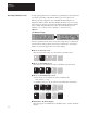
The Maintenance level allows access to all of the parameters listed in the
View and Modify levels in addition to the parameters listed below. Two
squares (
) will be present in the upper left corner of the display to
denote that this level is active (see Figure 6.1).
04 Adapter Type
05 Logic Command
06 Drive Faults
07 Drive Status
08 Auto Tune Status
17 Velocity Reference Whole
18 Velocity Reference Fraction
21 Filtered Velocity Feedback
22 Average Motor Velocity
23 Resolver Turns
24 Resolver Position Feedback
25 Pre Ramp Velocity
33 Proportional Velocity Error
34 Velocity Loop PI Output
35 Integral Velocity Error
44 External Torque Reference
46 Id (Flux) Current Reference
47 IT Protection Limit
48 Bridge Current Limit
49 Current Feedback Scale
58 D/A #1 Command Value
59 D/A #2 Command Value
129 Units Select
135 Up to Speed Tolerance
136 Drive Address
155 Rated Motor Current
158 Current Rate Limit
172 Velocity Loop Integrator Preset Value
181 Motor Inertia
199 Friction Compensation
200 Friction Hysteresis
201 Friction Bit
213 D/A #2 Gain
222 Id RPM Start
223 Id RPM End
224 Id Percent Limit
234 Transport Compensation
243 Indirect Sink Parameter 1
244 Indirect Source Parameter 1
245 Indirect Sink Parameter 2
246 Indirect Source Parameter 2
251 Access Timeout
252 Drive Init Stats
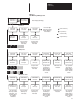
In addition to the three levels described, each level has additional auxiliary
menus. These menus allow quick access to important parameters such as
fault status and setup data. Refer to Figure 6.3 for further information.