
USER MNL/DIGITAL AC SERVO DR Manual


Chapter 11
Troubleshooting
11-10
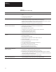
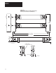
Table 11.E
Test Point Descriptions
Test Point Description
TP2 Resolver: 8.000 kHz sine wave 3.0V RMS
TP7 Triangle: Triangle oscillator 2.5kHz , 5.5 volts peak
TP8 PWM B: Phase B transistor turn on signal
TP9 PWM A: Phase A transistor turn on signal
TP10 PWM C: Phase C transistor turn on signal
TP11 +5V DC
TP12 Signal Common
TP13 +12V DC
TP14 –12V DC
TP15, 16 IALPHA and IBETA: Sinusoidally varying DC level representing the current
command to the current loop scaled for 2.5V peak =
rated motor current
TP17 IT Ref: Voltage representing current reduction amount
TP19 Buffered Output: Velocity input
TP20 Buffered Output: Torque input
TP21 Ext Current Limit: Indicates the external current limit command
(3V = rated)
TP28 Signal Common
TP29, 30 IA, IB Feedback Buffered motor current feedback signals scaled for 2.5
volts peak = rated motor current
TP31 Signal Common
TP50 ABS Rotor: Signal used to detect resolver loss. Nominal value =
2.596V. Trip point is approximately 0.8V.
TP51 9V Ref: Signal feeding output d/a’s reference
TP52 Microprocessor Reset: Momentarily ground to reset microprocessor
TP40 Sine (wt): 4.0 kHz 2.0 Vrms sine wave used for A Quad B
TP41 Sine (wt) Sine (theta): 2.0 Vrms modulated waveform used for A Quad B
TP42 Sine (wt) Cosine (theta): 2.0 Vrms modulated waveform used for A Quad B
TP60 Display Reset: Ground to reset display microprocessor
TP61 Test Result: Indicates a pass or fail result from a self test initialization