391-DES Digital AC Servo Drive User Manual
Important User Information Because of the variety of uses for this equipment and because of the differences between this solid-state equipment and electromechanical equipment, the user of and those responsible for applying this equipment must satisfy themselves as to the acceptability of each application and use of the equipment. In no event will Allen-Bradley Company be responsible or liable for indirect or consequential damages resulting from the use or application of this equipment.
Summary of Changes Summary of Changes Summary of Manual Changes 1-4 This release of the 1391-DES User Manual contains some new and updated information. The new and updated information is summarized in the table below. For further information, refer to the page numbers provided.
Chapter Introduction Manual Objectives This manual is meant to guide the interface, installation, programming and troubleshooting of a 1391-DES Digital AC Servo Drive. The contents are arranged in order from a general description of the drive to troubleshooting and maintenance. To assure successful installation and operation, the material presented must be thoroughly read and understood before proceeding. Particular attention must be directed to the Attention and Important statements contained within.
Chapter 1 Introduction General Precautions In addition to the precautions listed throughout this manual, the following statements which are general to the drive must be read and understood. ! ! ! ATTENTION: Only personnel familiar with the 1391-DES Digital Servo Drive and associated machinery should plan or implement the installation, start-up and subsequent maintenance of the drive. Failure to comply may result in personal injury and/or equipment damage.
Chapter 1 Introduction The 1391-DES is generally used with computer aided, closed loop positioning systems such as Allen-Bradley “S” Class or IMC products. These systems control the position and linear or rotary motion of various machine members on an automated machine. To enhance system reliability, the 1391-DES has an encoder output (AQB) that produces four channels of 2048, 1024, 512 or 256 lines and two marker pulses per motor revolution which feeds position information to the position controller.
Chapter 1 Introduction Options/Modifications The 1391-DES contains most functions needed in a servo system. The following are selectable at the user’s option: • Contactor Auxiliary Switch Two N.O. (normally open) contacts are mounted on the main power contactor and wired to the power terminal block. These contacts can be used in a motor brake control circuit or as an indicator that the contactor has closed.
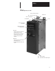
Chapter 1 Introduction Figure 1.1 1391-DES Digital AC Servo Drive Duty Cycle Selector Switch TB5 – Power Connections Ground Stud TB4 – Control Signals Circuit Breaker Fuses 2 Line, 16 Character LCD Display 5 Button Keypad used for Programming Status LED - Flashes green when no faults are present and the bus is low. - Steady green when no faults are present and bus voltage is OK. - Flashes red when a fault has occurred. Enable LED - Steady green when Enable input is closed at TB2-9 & 10.
Chapter 1 Introduction End of Chapter 1-10
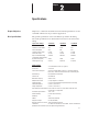
Chapter Specifications Chapter Objectives Chapter two contains the electrical and environmental specifications for the 1391-DES. Dimensions are provided in Appendix A. Drive Specifications The general specifications of the 1391-DES are provided in the listing below. The specifications are divided when necessary for the various drive ratings. Specific Drive Ratings 1391-DES15 1391-DES22 1391-DES45 Nominal Bus Voltage 300V DC 300V DC 300V DC Continuous Current (RMS) 15A 22.
Chapter 2 Specifications Environmental Specifications The 1391-DES must be mounted in an enclosure that is clean, dry and ventilated by filtered or cooled air. Enclosures vented with ambient air must have appropriate filtering to protect against contamination caused by oils, coolants, dust, condensation etc. The ambient air temperature must be kept between 0 to 60° C (32 to 140° F) and the humidity between 5 and 95%, non-condensing. The 1391-DES is equipped with an integral cooling fan.
Chapter Receiving, Unpacking and Inspection Chapter Objectives Chapter 3 provides the information needed to unpack, properly inspect and if necessary, store the 1391-DES and related equipment. The section entitled Inspection provides a complete explanation of the 1391-DES catalog numbering system. Receiving It is the responsibility of the user to thoroughly inspect the equipment before accepting the shipment from the freight company. Check the item(s) received against the purchase order.
Chapter 3 Receiving, Unpacking and Inspection Isolation Transformer 1391 – T 015 First Position Second Position Bulletin Number D T Third Position Fourth Position Fifth Position Type kVA Rating Primary Voltage & Frequency Secondary Voltage Letter Description Number kVA Letter Description Letter Description T 015 035 050 100 125 150 1.5 3.5 5.0 10.0 12.5 15.
Chapter 3 Receiving, Unpacking and Inspection Bulletin 1391-DES Drive 1391 – DES15 – DI – AQB – A First Position Second Position Third Position Fourth Position Fifth Position Bulletin Number Configuration/ Current Rating User Interface Output Configuration Options Code Code Description Code Letter Description DI Includes Integral Display AQB Encoder Output – 2048, 1024, 512, 256 selectable pulses/motor revolution A 24V DC M contactor coil voltage instead of 115V AC (available
Chapter 3 Receiving, Unpacking and Inspection 1326AB Torque Plus Series Servomotor 1326 AB – A 4 30 E First Position Second Position Third Position Fourth Position Fifth Position Sixth Position Seventh Position Eighth Position Bulletin Number Type Voltage Series Motor Length Max. Operating Speed Mounting & Shaft Description Standard Options Letter Description Code Rating Description Description Letter Rated/1391-DES Code AB A Sequentially lettered to designate frame diameters.
Chapter 3 Receiving, Unpacking and Inspection Motor Junction Box Kit 5 1326AB – MOD – RJAB First Position Second Position Third Position Bulletin Number Type Description Code Description Code MOD Modification Kit RJAB For all AB-A & B Series Motors (A4 & A5 Torque Plus Motors) RJB C 5 Description For all AB-B4 & Cx Series Motors (A7 Torque Plus Motors) The motor comes standard with IP65 plug style connectors mounted radially to the motor.
Chapter 3 Receiving, Unpacking and Inspection Feedback Coupling 7 1326 – MOD – First Position Second Position Third Position Bulletin Number Type Coupling Size Code Code Size – Motor Shaft to Encoder Shaft Description MOD Modification Kit 7 C1 C1 3/8” to 3/8” (9.5 mm to 9.5 mm) – Standard on all 1326AB Motors C2 1/4” to 3/8” (6.4 mm to 9.5 mm) The feedback coupling is included as standard with all Feedback Mounting Adapter Kits.
Chapter 3 Receiving, Unpacking and Inspection Power and Feedback Cables 1326 – C P AB T 15 First Position Second Position Third Position Fourth Position Fifth Position Sixth Position Bulletin Number Type Function Motor Size Used On Power Track Cable Cable Length Code Description Code Description Letter Description Code Type Letter Description Code Description 1326 Standard Cable C P AB Series A & B (except 1326AB-B4) T All Series, used for high flex applications K Conne
Chapter 3 Receiving, Unpacking and Inspection Planetary Gearbox 1326AB – PG A 05 – LB – 21 First Position Second Position Third Position Fourth Position Fifth Position Sixth Position Bulletin Number Type Used on 1326AB Motor Series Gear Ratio (Motor Shaft:Output Shaft) Options Adapter Code Description Code Standard Torque Plus Code Description Code Code Description A Series A -A4 10 Metric LB 11 English C -A7 10 3:1 5:1 10:1 15:1 20:1 30:1 50:1 100:1 21 Series B -A5 10
Table of Contents Introduction Chapter 1 Manual Objectives . . . . . . . . . . . . . . . . . . . . . . . . . . . . . . . . . . . . . . . . . General Precautions . . . . . . . . . . . . . . . . . . . . . . . . . . . . . . . . . . . . . . . . Drive Description . . . . . . . . . . . . . . . . . . . . . . . . . . . . . . . . . . . . . . . . . . Standard Features . . . . . . . . . . . . . . . . . . . . . . . . . . . . . . . . . . . . . . . . . . Options/Modifications . . . . . . . . . . . . . . . . . . . . . .
Table of Contents Programming Chapter 6 Chapter Objectives . . . . . . . . . . . . . . . . . . . . . . . . . . . . . . . . . . . . . . . . . Display Description . . . . . . . . . . . . . . . . . . . . . . . . . . . . . . . . . . . . . . . . Keypad Description . . . . . . . . . . . . . . . . . . . . . . . . . . . . . . . . . . . . . . . . Parameter Levels . . . . . . . . . . . . . . . . . . . . . . . . . . . . . . . . . . . . . . . . . . Accessing Parameter Levels . . . . . . . . . . . . . . . . . . . . .
Chapter Description of Operation Chapter Objectives Chapter 4 is intended to familiarize the reader with the circuitry of the 1391-DES in terms of function and operation. General The intended use of the 1391-DES is to control the speed and torque of an AC servomotor in a closed loop position system. A complete servo system can be configured with a 1391-DES Servo Drive, 1326 AC Servomotor and 1391 Isolation Transformer. Refer to the 1391-DES Block Diagram presented in Figure 4.4 for general layout.
Chapter 4 Description of Operation Figure 4.1 PWM Waveform 300V DC Bus 400µs Typical 400µs Typical Time 0 400µs Typical 400µs Typical The three-phase relationship between the reference signal and the timing wave provide PWM pulses to the power transistor base drive. This base drive switches the power transistors across the 300V DC bus, providing current to the motor windings, thus causing the motor to turn.
Chapter 4 Description of Operation Shunt Regulator Operation The 1391-DES shunt regulator provides power dissipation for regenerative conditions when the energy returned to the drive by the motor exceeds that which can be stored in the bus capacitors. The shunt regulator monitors the bus voltage and at a predetermined “ON” point activates the shunt regulator transistor, allowing current to flow through the shunt resistor and dissipating power in the form of heat.
Chapter 4 Description of Operation Overtemperature The drive contains a thermal switch on the heat sink which indirectly senses transistor module temperature. If the temperature rating of the switch is exceeded, the DROK contact opens and the drive is disabled. Power Fault A fault related to the power bridge section of the drive will cause the drive to be disabled and open the DROK contact. Control Voltage Fault If the control voltage varies more than ±10% of the nominal 12V DC, this fault will occur.
Chapter 4 Description of Operation Microprocessor Control The 1391-DES is controlled by an 80C196KB microprocessor. Velocity control, sequencing, fault logic, programming and option control is performed by the processor. Current control is analog, as is the input velocity command. The input command is fed through a 14 bit digital to analog converter (13 bits/8192 resolution and a +/– sign bit).
Chapter 4 Description of Operation ! ATTENTION: The user has the ultimate responsibility to determine which stopping method is best suited to the application and will meet applicable standards for operator safety. Starting and Stopping must be accomplished by hardwired user supplied elements as shown in Appendix B. Stopping modes for the 1391-DES are outlined below. Refer to the paragraphs that follow for detailed information.
Chapter 4 Description of Operation Power-Up/Down Sequence Figure 4.3 describes the various steps involved in the power-up/down sequence of the 1391-DES Drive. Figure 4.3 Drive Power-Up / Down Sequence POWER-UP SEQUENCE POWER-DOWN SEQUENCE Apply AC Input Power to Isolation Transformer a) Logic power supplies and base drive circuits power-up. b) Apply 115V AC to contactor. c) Power bus charges. d) If no faults are encountered, the DROK relay energizes. Drive is ready to receive customer enable signal.
Chapter 4 Description of Operation Figure 4.
Chapter Inputs, Outputs and Switch Settings Chapter Objectives Chapter 5 contains descriptions of the various inputs and outputs available on the 1391-DES Digital Servo Drive. Additionally, information for properly setting the drive switches is provided for reference when you perform start-up. For information on shunt regulator adjustments, refer to Chapter 10. Inputs/Outputs The following paragraphs provide detailed descriptions of the various inputs and outputs available for the 1391-DES.
Chapter 5 Inputs, Outputs and Switch Settings Analog Out 2 (Current) (TB2, Terminal 6) A voltage corresponding to positive and negative current will be present at this terminal and signal common (Terminal 7). +3V DC equals 100% of the continuous rating of the motor with +6V DC equaling 200%. Minimum impedance that can be placed across this output is 10k ohm.
Chapter 5 Inputs, Outputs and Switch Settings Terminal Block - TB3 (A Quad B Board) Figure 5.1 provides interconnect information between the position controller and TB3 on the A Quad B Board. ATTENTION: To guard against possible damage to the A Quad B Board, assure that wiring between TB3 and the position controller is correct. Refer to Figure 5.1. ! Figure 5.
Chapter 5 Inputs, Outputs and Switch Settings “M” Contactor Auxiliary Contacts (TB4, Terminals 13, 14, 15, 16) The auxiliary contacts of the integral contactor are accessed through these terminals. Refer to Table 5.A for contact ratings. Table 5.A “M” Contact Ratings (minimum 50 mA at all voltages) DC Ratings AC Ratings Volts (Ue) Amperes (Ie) Volts (Ue) Amperes (Ie) 12-120 220-240 380-480 500-600 6 3 1.5 1.2 28 110 220 440 660 5.0 1.25 0.62 0.27 0.
Chapter 5 Inputs, Outputs and Switch Settings Figure 5.2 Terminal Block, Circuit Board and Switch Locations TB1 1 Main Logic Control Board Display Board A Quad B Board Memory Board 1 12 TB3 1 S1 TB2 Ground Stud Top View of Controller TB5 1 1 10 SW1 11 TB4 MCB 22 F3 provided on 15 & 22.5A units only 15A = Bussmann KLM10 or equivalent 22.
Chapter 5 Inputs, Outputs and Switch Settings Switch Settings This section provides information on setting the Duty Cycle Selector switch (SW1) and the A Quad B Encoder Output switch (S1). Note that the settings for 1326AP motors are the same as 1326AB motors. Refer to Figure 5.2 for switch locations. Duty Cycle Selector Switch - SW1 The Duty Cycle Selector Switch (SW1) which is located on top of the drive, modifies the behavior of the shunt regulator.
Chapter 5 Inputs, Outputs and Switch Settings When using the A Quad B option with Allen-Bradley IMC motion controllers, the AMP parameters will be set according to the line count selected. In general, one parameter must be justified when using this device. Important: For all IMC classic products (IMC 110, 12x) the normal line counts per cycle of the encoder must be divided by two since the drive will see two markers per cycle.
Chapter 5 Inputs, Outputs and Switch Settings End of Chapter 5-8
Chapter Programming Chapter Objectives This chapter explains the programming/setup system of the 1391-DES Digital AC Servo Drive. Included is an explanation of the display, general programming procedure and description of the programmable parameters. You will need to read this chapter before performing the start-up procedure provided in Chapter 8. Display Description The 1391-DES display is used for programming, as well as status and diagnostic messages.
Chapter 6 Programming Figure 6.2 1391-DES Display Panel Display Keypad Up Arrow Key This key is used to increase values when modifying parameters. Other uses will be described when applicable. Down Arrow Key The Down Arrow key is used to activate modifiable parameters or decrease values. Other uses will be described as required. Left Arrow Key This key is used to scroll through parameters or move the cursor when modifying parameters. Other key functions will be described as needed.
Chapter 6 Programming Parameter Levels For ease of use, the various parameters of the 1391-DES are numbered and arranged in three different levels. The levels range from viewing simple drive status parameters to more complex setup information. The three levels are as follows: View Level The View level allows viewing only of the drive operating conditions (see below). The View level is denoted on the display by a single dot ( ) in the upper left corner (see Figure 6.1).
Chapter 6 Programming 212 233 D/A #1 Gain Cable Compensation Maintenance Level The Maintenance level allows access to all of the parameters listed in the View and Modify levels in addition to the parameters listed below. Two squares ( ) will be present in the upper left corner of the display to denote that this level is active (see Figure 6.1).
Chapter 6 Programming Figure 6.
Chapter 6 Programming Accessing Parameter Levels To help guard against access to advanced programming levels by untrained personnel, special key combinations must be pressed to gain access. When power is first applied to the 1391-DES the Basic Display (see Figure 6.4) will be shown. The Basic Display alternates (every 2 seconds) between the two displays shown. The alternating display indicates that the drive is functioning normally.
Chapter 6 Programming Programming Important: Programming of most 1391-DES parameters is not required. When power is initially applied to the drive, a prompted start-up procedure will occur (first time only). The display will guide the user through this procedure, which will set all of the main parameters for machine operation. Parameters listed in this chapter are essentially for reference only. Follow the Start-Up Procedure in Chapter 8 before attempting to change any parameters.
Chapter 6 Programming Parameter Descriptions This section lists and describes the various parameters currently available (software version 2.01). Not all parameters will be available in every parameter level. Refer to the “Parameter Type” classification in each description for further information. In addition to the Parameter Type, each description (when applicable) will also provide Minimum, Maximum and Default Values.
Chapter 6 Programming Parameter 06 – Drive Faults (Drv Faults) * Parameter 06 is a 16 bit, binary word that represents the drive faults. A “1” indicates that a fault has occurred. If a “0” is displayed, a fault has not occurred. Refer to the list below for an explanation of the individual bits.
Chapter 6 Programming Parameter 08 – Auto Tune Status (ATn Status) * A 16 bit, binary word represents the auto tune status. A “1” indicates that a particular state exists. If a “0” is displayed, that state does not exist. Refer to the list below for an explanation of the individual bits.
Chapter 6 Programming Parameter 20 – Velocity Feedback (Vel Feedback) * The unfiltered motor velocity is displayed through this parameter. Parameter Type: Minimum Value: Maximum Value: View only, all levels –8000 rpm +8000 rpm Parameter 21 – Filtered Velocity Feedback (Filtrd Vel Fb) * The filtered velocity feedback which is output by the lead/lag filter is supplied by this parameter. The bandwidth of the filter is specified by parameter 186 and the filter gain is specified by parameter 185.
Chapter 6 Programming Parameter 34 – Velocity Loop PI Output (Vel PI Output) * Indicates the latest output of the velocity PI regulator. Parameter Type: Minimum Value: Maximum Value: View only in Maintenance level –8000 rpm +8000 rpm Parameter 35 – Integral Velocity Error (Intg Vel Error) * The error between the Final Velocity Command (parameter 19) and the Velocity Feedback (parameter 20) is supplied by this parameter.
Chapter 6 Programming Parameter 49 – Current Feedback Scale (Cur Fdbk Scale) * The current feedback scaling is displayed based on motor current rating and drive size (parameters 155 & 3). See Table 6.A. Parameter Type: Minimum Value: Maximum Value: View only in Maintenance level 0 15 Table 6.A Typical Current Feedback Scaling Motor Rated Current 1391-DES15 1391-DES22 1391-DES45 Parameter 49 Value 15.0 14.1 13.1 12.2 22.5 21.1 19.7 18.3 45.0 42.2 39.4 36.6 15 14 13 12 11.3 10.3 9.4 8.4 16.9 15.
Chapter 6 Programming Parameter 58 – D/A #1 Command Value (D/A 1 Cmd Val) * This parameter displays the actual value input to D/A Converter 1. Parameter Type: Minimum Value: Maximum Value: View only in Maintenance level –2047 +2047 Parameter 59 – D/A #2 Command Value (D/A 2 Cmd Val) * This parameter displays the actual value input to D/A Converter 2. Parameter Type: Minimum Value: Maximum Value: View only in Maintenance level –2047 +2047 Parameter 68 – Bandwidth Maximum (Bandwidth Max.
Chapter 6 Programming Parameter 130 – Drive OK Mode This parameter specifies how the Drive OK (DROK) relay is controlled. If the parameter is set to “0,” the relay will be opened when a fault occurs. If the parameter is set to “1,” the relay will open when a fault occurs and there is not sufficient DC bus voltage.
Chapter 6 Programming Parameter 136 – Drive Address * This parameter is not active at this time. Parameter Type: Minimum Value: Maximum Value: Default Value: View/modify in Maintenance level 1 14 1 Parameter 144 – Clockwise Velocity Limit (CW Vel Limit) Specifies maximum velocity reference in the clockwise (positive) direction.
Chapter 6 Programming Parameter 156 – Positive Current Limit (Pos. Cur Limit) Parameter 156 specifies the maximum allowable positive motor current that can be commanded. If greater than parameter 48, parameter 48 will then set the limits.
Chapter 6 Programming Parameter 169 – Kl Velocity Loop (Intg Gain ki) This parameter controls the integral error gain of the velocity regulator. For example, if KI = 8, then velocity (1000 rpm) error for 1 second will produce a (rated motor) current torque reference. Parameter Type: Minimum Value: Maximum Value: Default Value: View/modify in Modify level and Maintenance level 0 24000 6667 Parameter 170 – Feed Forward Gain (Feed Frwd Gain) Controls the feedforward gain of the velocity regulator.
Chapter 6 Programming Parameter 183 – Velocity Damping Selection (Vel Damp Selct) This parameter is associated with the auto tune function and specifies the velocity damping desired by the user. The auto tuning procedure calculates a new set of Velocity Loop Gains (parameters 168 & 169) and a new Current Rate Limit (parameter 158) when the user initiates the Auto Tune Calculate function. Refer to Figure 8.1 for further information.
Chapter 6 Programming Parameter 188 – Auto Tune Current Limit (Auto Tune Cur) The motor current used while an auto tune cycle is executing is specified with this parameter.
Chapter 6 Programming Parameter 201 – Friction Bit (Frictn Bit) The number of bits surrounding Friction Hysteresis (parameter 200). Parameter Type: Minimum Value: Maximum Value: Default Value: View/modify in Maintenance level 0 50 10 Parameter 210 – Analog to Digital Converter Offset (Anlg Vel Offst) This parameter adds an offset to the A/D converter value to correct for input A/D offset and user input command D/A output offset.
Chapter 6 Programming Parameter 213 – Digital to Analog #2 Gain (D/A 2 Gain) This parameter scales the D/A #2 Command Value (parameter 59) before it is output to D/A Converter 2. To change scaling: Desired Voltage /Rated Current x 0.05553. Parameter Type: Minimum Value: Maximum Value: Default Value: View/modify in Maintenance level gain of –14.6 gain of +14.6 gain of +0.167 Parameter 222 – Id RPM Start * This parameter is associated with the field weakening function.
Chapter 6 Programming Parameter 243 – Indirect Sink Parameter 1 (Indirect Sink1) * This parameter specifies the sink parameter for Indirect Link 1. Parameters 243 and 244 define a link between two other parameters. The value of the parameter specified by parameter 244 is written to the parameter specified by parameter 243 once every velocity loop update.
Chapter 6 Programming Parameter 252 – Drive Initialization Status (Drv Init Stats) This parameter specifies if the drive has gone through an out-of-the-box start-up procedure (defined in Chapter 8). Parameter Type: Default Value: 1 0 View/modify in Maintenance level 1 No No – has not been setup Yes – has been setup Parameter 253 – Display Software Version (Display SW Ver) * This parameter displays the current display software version number.
Chapter Chapter 7 Installation Chapter Objectives Chapter 7 provides the information needed to help properly mount and wire the 1391-DES Servo Drive for operation. Since most start-up difficulties are the result of incorrect wiring, every precaution must be taken to assure that the wiring is done as instructed. All items must be read and thoroughly understood before the actual installation begins. ! Mounting ATTENTION: The following information is merely a guide for proper installation.
Chapter 7 Installation ! 7-2 ATTENTION: The installation of the drive must be planned such that all cutting, drilling, tapping and welding can be accomplished with the drive removed from the enclosure. The drive is of the open type construction and any metal debris must be kept from falling into it. Metal debris or other foreign matter may become lodged in the circuitry resulting in component damage.
Chapter 7 Installation Wiring Recommendations General Information The information supplied in this manual on wire sizes, practices, layouts, system configurations and grounding/shielding techniques for the 1391-DES Servo Drive are presented as guidelines. Due to the diversity of applications and systems, no single method of wiring is completely applicable.
Chapter 7 Installation Open ended shields (resolver feedback cable at the resolver and velocity command cable at the servo drive) must be insulated so that they do not accidentally cause ground loops. EMI Shielding The 1391-DES has an inverter carrier frequency of 2500 Hz. Therefore, the system may induce noise into sensitive equipment lines adjacent to it.
Chapter 7 Installation The Interconnect Drawing presented in Appendix B provides typical interconnection wiring for the 1391-DES AC Servo Drive. Typical control logic circuitry (starting and stopping), motor interconnections and grounding techniques are shown. Please note that the drive circuit breaker (MCB) is not designed or intended to meet branch circuit protection requirements. The circuit breaker protects the DC bus supply, input rectifier and power circuitry against overcurrents.
Chapter 7 Installation Motor Feedback Wiring Connections to the integral commutation resolver must be made using an Allen-Bradley 1326-CFUxx shielded cable. ! ATTENTION: To guard against hazard of personal injury or damage to equipment, the interconnections to the motor and resolver must be made exactly as shown in Appendix B. Failure to do so could cause loss of motor control and/or severe oscillation of the motor shaft. Encoder (A Quad B Board) Wiring Recommended Wire – Belden #9728 or equivalent.
Chapter 7 Installation Table 7.B Minimum Transformer Wire Sizes – AWG (mm2) kVA Input Voltage 1.5 3.5 5.0 10.0 12.5 15.0 208V AC #12 (2.5) #12 (2.5) #12 (2.5) #8 (6) #8 (6) #6 (10) 240V AC #12 (2.5) #12 (2.5) #12 (2.5) #8 (6) #8 (6) #8 (6) 380V AC #12 (2.5) #12 (2.5) #12 (2.5) #10 (4) #10 (4) #8 (6) 415V AC #12 (2.5) #12 (2.5) #12 (2.5) #12 (2.5) #10 (4) #10 (4) 480V AC #12 (2.5) #12 (2.5) #12 (2.5) #12 (2.5) #10 (4) #10 (4) 575V AC #12 (2.5) #12 (2.5) #12 (2.
Chapter 8 Start-Up Chapter Objectives Chapter 8 provides the steps needed to help properly start-up the 1391-DES Digital AC Servo Drive. Included in the procedure are typical adjustments and voltage checks to assure proper operation. The information contained in Chapters 5, 6 and 7 must be read and understood before proceeding. Start-Up Procedure The following procedure provides the required steps to start-up the 1391-DES AC Servo Drive in velocity and position mode.
Chapter 8 Start-Up 2. Check terminal block connections as described in Chapter 5 and Appendix B. 3. Set switches S1 (A Quad B Board) and SW1 (top of drive) as explained in Switch Settings in Chapter 5 4. Assure that the drive circuit breaker (MCB), contactor (M) and Enable input are OFF (de-energized). 5. Apply power to the input transformer primary, but Do Not Enable the drive or energize the contactor (M). The Enable LED should be Off. 6.
Chapter 8 Start-Up 10. The drive will now prompt you through a start-up procedure. Read the following important points before continuing. • From time to time the drive will display the message “EEprom Fnction in progress.” This message alerts the user that an EEprom function is in progress and that operation will return to normal momentarily. If the message “drive can’t be running for EE” is displayed, verify that the drive is disabled. • If the drive faults during start-up (i.e. feedback miswired, etc.
Chapter 8 Start-Up ! ATTENTION: In the following steps, reverse rotation or uncontrolled rotation at high speed can occur. Be prepared to remove drive power by opening (MCB) or the branch circuit disconnect device if this occurs. This movement may be due to a wiring error or system component malfunction and must be corrected before proceeding. Damage to machine system components can occur due to uncontrolled machine movements. 13.
Chapter 8 Start-Up 17. The display will now read “enter parameter information” – press the Enter key to continue. The drive will allow you to enter a value for the Analog Velocity Gain. The desired input velocity command voltage to motor rpm scaling is accomplished with the Analog Velocity Gain parameter (211). The default setting is 500 rpm/volt. Use the following formula if the maximum motor speed (rpm) and maximum velocity command (volts) are known.
Chapter 8 Start-Up 22. Display: “autotune the servo drive” – press Enter to continue. Assure that the drive Enable input is de-energized and the contactor (M) is energized. The drive will display the message “drive not ready to tune” if this has not been done. The drive will prompt you for Auto Tune Current Limit. This current is used for auto tuning only. The default value displayed is sufficient, however, a different value of up to 100% of motor rating can be entered if desired.
Chapter 8 Start-Up 26. The drive will display the Bandwidth Max. parameter (68). The value displayed is the maximum bandwidth, in rads/sec. your system can achieve. Record this value for future reference and press Enter. Bandwidth Maximum = rads/sec. (rads/sec. can be converted to Hertz (Hz) by dividing by 6.28) 27. The drive will display the Desired Velocity BW (182). Enter any value of bandwidth up to the value of Bandwidth Max. from above. Values greater than Bandwidth Max. will be ignored.
Chapter 8 Start-Up Manual Tuning Procedure If manual tuning of certain parameters is required, the following procedure can be followed after all of the previous steps have been performed. Parameters referenced in the following steps are located in the Modify programming level. This level can be reached from the View level by pressing the Up, Down and Left Arrow keys, simultaneously. 32. Zero Speed Adjust a) Remove all power from the drive.
Chapter 8 Start-Up 34. Clockwise/Counterclockwise Velocity Limits a) Apply power to the drive. b) Energize the contactor (M), but Do Not Enable the drive. c) Access parameters 144 and 145 (Clockwise/Counterclockwise Velocity Limits) to enter the maximum speed limit of the motor at maximum velocity command. If the maximum command voltage exceeds the normal maximum level, these values will limit the speed of the motor. d) Perform step 36. e) Remove power and reconnect all wiring, if applicable. 35.
Chapter 8 Start-Up ATTENTION: If an oscilloscope (or chart recorder) is used during Start-Up or Troubleshooting, it must be properly grounded. The oscilloscope chassis may be at a potentially fatal voltage if not properly grounded. Always connect the oscilloscope chassis to earth ground. ! When using an oscilloscope (or chart recorder) it is recommended that the test probe ground be connected to TB2-5. 38.
Chapter 8 Start-Up Linear Accel/Decel Control Module The following information explains manual controller operation with the Linear Accel/Decel Control Module (CR-APG-001). This module provides adjustable acceleration/deceleration control for the 1391-DES. Up to four remote or local preset speeds are available. Important: The 1391-DES Accel/Decel Ramp parameter (146) locally controls the velocity command per time rate. The default value is set to a maximum of 22216 revs per sec/sec.
Chapter 8 Start-Up To select Local Speed a) Energize the speed select input, SEL 1 (terminals 1 & 2 of J2) with either 24V DC or 115V AC. The front panel “SEL 1” LED will illuminate. b) Repeat the above step for any of the other three preset speeds. Important: If more than one speed is selected at the same time, the resulting speed for the velocity profile will not be predictable. Important: In the following steps, the local speed control (SPD 1) will be used.
Chapter 8 Start-Up 12. The output of the module is controlled by the “Deadman” input at terminals 10 & 11 of J1. Applying 24V DC or 115V AC to this input will cause the module to operate. The front panel “Dedman” LED will be off. When this input is de-energized, the module output will be connected to logic ground, thus disabling output. At this point the “Dedman” LED will illuminate. Energize the “Deadman” input with 24V DC or 115V AC. ! 13.
Chapter 8 Start-Up Figure 8.2 Linear Accel/Decel Control Module Wiring J1 +10V DC 9 1 2 SPD 1 Remote Speed 1 Local Remote Select 1 24V DC or 115V AC Direction Change Speed Select 1 J2 Local Speed 1 Direction Change Select J1 3 4 SPD 2 Remote Speed 2 Local Remote Select 2 Speed Select 2 FWD./REV.
Chapter 8 Start-Up Figure 8.3 Linear Accel/Decel Control Module Dimensions 4.25 (108.0) 0.41 (10.3) 3.44 (87.3) 0.50 (12.7) 8.12 (206.2) 7.25 (184.2) Dimensions are in inches (mm) 0.75 (19.1) 2.75 (69.9) 0.75 (19.1) 0.5 (12.
Chapter 8 Start-Up End of Chapter 8-16
Chapter 9 1326 AC Servomotors Chapter Objectives Chapter 9 describes the operation of a standard 1326 AC Servomotor with the enhanced capabilities of a Bulletin 1391-DES Digital AC Servo Drive. Refer to the 1326 AC Servomotor Product Data for further information on Allen-Bradley AC Servomotors. Introduction The 1391-DES provides additional energy to the 1326 motor, allowing it to operate at higher speeds without a reduction of torque.
Chapter 9 1326 AC Servomotors Tc – rated torque of motor with windings at rated temperature and an ambient of 40°C. The drive is operating in a rated ambient of 60°C. Tp – the peak torque that can be produced by the motor/drive combination with both at rated temperature and the motor in a 40°C ambient and the drive in a 60°C ambient. Higher peak torques are permissible where RMS torque is less than or equal to the rated torque (Tc).
Chapter 9 1326 AC Servomotors Table 9.A provides a comparison of the resultant speed obtained from standard 1326 servomotors using 1391 and 1391-DES Servo Drives. Table 9.B provides performance data for the 1326AB Torque Plus Series Motors. Table 9.A 1391/1391-DES Speed Comparison 1, 2 Continuous Stall Torque (lb.-in./N-m) Peak Stall Torque (lb.-in./N-m) Mtr.
Chapter 9 1326 AC Servomotors End of Chapter 9-4
Chapter 10 Transformers and Shunt Regulators Chapter Objectives Chapter 10 provides general information about the 1391 Isolation Transformer. In addition, shunt regulator information is also provided. 1391 Transformers The 1391-DES must operate from an isolation transformer having a three-phase, 230V AC output and a single-phase, 36V AC output. Transformers supplied with the 1391-DES can provide power for up to four drives. Standard three-phase input voltages for the 60 Hz units are available.
Chapter 10 Transformers and Shunt Regulators Figure 10.1 1391 Transformer Wiring Diagrams 1 1391–TxxxDT (60 Hz.) Primary Voltage 240V AC Connect H1 to H3 to H8 H2 to H4 to H6 H5 to H7 to H9 H2 to H3 H5 to H6 H8 to H9 480V AC H1 H3 H2 H4 H6 H5 H7 H9 H8 Lines On H1 H4 H7 H1 H4 H7 P1 P2 G0 Thermal switch for transformer protection (rated 115V AC/1A, 24V DC/0.25A min., 185_C ±5_C G1 Faraday Shield G2 Y2 X1 X2 X0 230V AC X3 Y1 Y3 1391–TxxxET (50/60 Hz.
Chapter 10 Transformers and Shunt Regulators Shunt Regulator Operation Refer to Chapter 4 for an explanation of the shunt regulator circuitry. The nominal data for the shunt regulator is as follows:. Overvoltage Trip Point DC Bus Shunt “ON” Point DC Bus Shunt “OFF” Point Nominal DC Bus Voltage DC Bus Undervoltage Detect = 405V DC±2.5% = 386.4V DC = 366.9V DC = 300V DC = 145V DC±20% The shunt regulator behavior is modified by an adjustable duty cycle timer.
Chapter 10 Transformers and Shunt Regulators Table 10.B shows the nominal resistor power trip levels in watts for the various switch settings. When shunt requirements exceed the selector setting, the excess power will cause the bus voltage to rise, resulting in an overvoltage fault condition and loss of braking. Table 10.B Nominal Power Trip Level Reference Data (continuous watts,±10%)* SW1 Switch Setting 15A W/ Int. 16 Ohm Resistor 22.5A W/ Int. 12 Ohm Resistor 22.5A W/ Ext.
Chapter 10 Transformers and Shunt Regulators Frequent overvoltage trips and blown fuse on high inertia systems during regenerative states (deceleration) may be an indication that an external shunt resistor having increased power dissipation capacity is required. Based on the data supplied, Allen-Bradley will specify a shunt resistor with the proper resistance value for the drive being used.
Chapter 10 Transformers and Shunt Regulators ! ATTENTION: Proper derating must be applied to the manufacturers nominal resistor power ratings when using these in external shunt configurations. Consult the resistor manufacturer for recommended derating. Failure to comply could result in personal injury and/or equipment damage from an overheated resistor. Shunt Fusing Shunt regulator fusing is provided with all of the 1391-DES drives.
Chapter 11 Troubleshooting Chapter Objectives Chapter 11 provides information to guide the user in troubleshooting the 1391-DES. Included in the chapter are board and drive substitution procedures, fault indications, general system faults and test point descriptions. System Troubleshooting Most drive faults are annunciated by fault messages on the front panel display. Many system malfunctions manifest themselves through a drive fault.
Chapter 11 Troubleshooting The majority of faults cause the DROK contact to operate. The use of fault messages may aid in identifying drive and motor malfunctions. If a drive fault occurs, the fault detection circuitry can be reset by removing and reapplying power to the transformer supplying the servo drive or connecting the Reset input (TB2-11) to ground (TB2-12) with the enable removed.
Chapter 11 Troubleshooting Display Board Substitution 1. Remove all power to the drive branch circuit. 2. Remove the front cover from the drive. 3. Loosen the 4 thumb screws and remove the cable between the Display and Logic Control Boards. Remove the Display Board. 4. Install the new Display Board. Reconnect cable. 5. Apply power to the system and check for proper operation – tuning is not be required. Memory Board Substitution 1. Remove all power to the drive branch circuit. 2.
Chapter 11 Troubleshooting A Quad B Board Substitution 1. Remove all power to the drive branch circuit. 2. Remove the front cover from the drive. Label and remove the ribbon cables and signal connectors (TB1, TB2 and TB3) from the A Quad B and Logic Control Boards. 3. Remove the Display and Logic Control Boards. 4. Remove the A Quad B Board. 5. Install the new A Quad B Board to the Logic Control Board with the 8 thumb screws. 6.
Chapter 11 Troubleshooting Table 11.A LED Fault Diagnostics Enable The application of an Enable signal by the machine position controller will cause the ENABLE LED to illuminate. Enable LED is NOT Illuminated 1. 2. 3. 4. The position controller has not enabled the drive. The Enable wiring to the drive is open. The position controller Enable relay/switch has malfunctioned. The position controller has detected a machine system malfunction that will not allow the drives to be Enabled. 5.
Chapter 11 Troubleshooting Troubleshooting Tables Table 11.B provides a listing and description of the faults shown through the front panel display. Also included are possible solutions to the faults. Table 11.C provides a listing of common system malfunctions and their possible causes. Table 11.D lists servomotor malfunctions and their possible causes. Table 11.E provides a listing and description of the available test points. Refer to Figure 11.1 for board, connector and test point locations.
Chapter 11 Troubleshooting Table 11.B Fault Descriptions and Diagnostics (Continued) Fault/Message Fault Description Potential Cause Overvoltage “bus overvoltage” (Bit 8) The DC Power Bus is continuously monitored. If it exceeds a preset level a fault is sensed and the power supply is disabled. The power bus voltage has exceeded 405V DC. 1. Power Driver Board is malfunctioning and incorrectly sensing the bus voltage. 2.
Chapter 11 Troubleshooting Table 11.C General System Troubleshooting Condition Possible Cause Axis or System runs uncontrollably 1. The velocity feedback, position feedback device or velocity command signal wiring is incorrect or open. 2. An internal drive malfunction exists. 3. Set in torque mode incorrectly. Axis or System is unstable 1. Parameters 168, 169 and 170 are set too high. 2. Position Loop Gain or Position Controller accel/decel rate is improperly set. 3.
Chapter 11 Troubleshooting Table 11.D General Servomotor Troubleshooting Condition Possible Cause No Rotation 1. 2. 3. 4. 5. Overheating 1. The rotor is partially demagnetized causing excessive motor current. 2. Motor voltage is exceeding the maximum value. 3. The duty cycle is excessive. Abnormal Noise 1. 2. 3. 4. Loose parts are present in the motor. Through bolts are loose. The bearings are worn. Parameters 168, 169 and 170 are set too high.
Chapter 11 Troubleshooting Table 11.E Test Point Descriptions 11-10 Test Point Description TP2 Resolver: 8.000 kHz sine wave 3.0V RMS TP7 Triangle: Triangle oscillator 2.5kHz , 5.
Chapter 11 Troubleshooting Figure 11.1 1391-DES Test Point Locations TB1 1 TP50 TP11 TP2 Display Board TP52 TP28 A Quad B Board TP11 TP60 Main Logic Control Board TP12 TP61 Memory Board TP13 TP29 TP14 TP12 TP30 TP8 TP9 TP10 TP7 TP16 TP15 TP19 TP11 TP20 TP31 TP21 TP40 TP13 TP51 TP42 12 1 TB3 1 S1 TB2 TP14 TP41 TP12 Ground Stud Top View of Controller TB5 1 10 SW1 11 TB4 MCB 1 F3 provided on 15 & 22.5A units only 15A = Bussmann KLM10 or equivalent 22.
Chapter 11 Troubleshooting End of Chapter 11-12
Appendix A Dimensions Figure A.1 1391-DES Dimensions Dimensions are in inches and (millimeters) Detail A 0.25 (6.3) Detail B 0.312 (7.9) Dia. 0.312 (7.9) Dia. 0.39 (9.9) 6.00 (152.4) 0.60 (15.2) Dia. 5.20 (132.1) 0.30 (7.6) 3.70 (93.9) See Detail A Ground Stud ALLEN–BRADLEY 19.00 (482.6) Status Enable 18.40 (467.4) 1391 DIGITAL AC SERVO DRIVE 17.13 (435.1) See Detail B 4.50 (114.3) 0.67 (17.0) 9.10 (228.6) 6.20 (157.5) 0.85 (21.6) 11.56 (293.6) Notes: 1.
Appendix A Dimensions Figure A.2 1391 Isolation Transformer Dimensions Dimensions are in inches and (millimeters) Slot PRIMARY VOLTAGE 0.22 (5.6) R CAT. NO. FREQUENCY POWER RATING CONNECT LINE INPUT ON TERM. 120 H1 TO H3 H2 TO H4 H1 & H4 240 H2 TO H3 H1 & H4 SECONDARY VOLTAGE B Max. VOLTAGE OUT OF TERMINALS PRIMARY VOLTAGE +5% X0 & X3 NOM. X0 & X2 –5% X0 & X1 SECONDARY VOLTAGE INSULATION CLASS 0.53 (13.5) NO. OF PHASES VENDOR PART NO. ALLEN–BRADLEY 0.44 (11.2) Ref. D E C Max.
Appendix A Dimensions Figure A.3 NEMA Type 1 Enclosure Dimensions Dimensions are in inches and (millimeters) The following items are included with the NEMA Type 1 Enclosure. Qty. Description 2 Steel Mounting Channels 4 3/8-16 x 1.0 HHCS Screw 4 3/8-16 x 1.5 HHCS Screw 8 3/8 Flat Washer 8 3/8 Split Lock Washer 8 3/8-16 Hex Nuts B C Front Side A E D Catalog Number kVA A B C D E Weight 1391-TA2 All 17.00 (432) 19.00 (483) 14.50 (368) 16.50 (419) 12.00 (305) 35.5 (16.
Appendix A Dimensions Figure A.4 External Shunt Resistor and Fuse Dimensions Dimensions are in inches and (millimeters) 5.38 (136.6) 12.75 (323.8) 14.00 (355.6) 2.25 1.13 (57.1) (28.7) 1.87 (47.5) 0.281 x 0.562 (7.1 x 14.2) 0.203 (5.2) Dia. w/ 0.343 (8.7) Dia. C.B. 2.81 (71.4) 0.91 (23.1) A-4 0.16 (4.1) 1.34 (34.
Appendix B Interconnect Drawings Objectives Appendix B provides typical interconnection diagrams that illustrate the wiring between the 1391-DES and various other Allen-Bradley position control products. Due to the numerous electrical circuit designs possible, these diagrams are provided for reference only. The diagrams provided include: - 1391-DES interconnect drawing showing the inputs, outputs and recommended control circuitry.
Appendix B Interconnect Drawings Figure B.
Appendix B Interconnect Drawings TYPICAL CONTROL CIRCUIT BRANCH CIRCUIT DISCONNECT 115V AC, 50/60 HZ. STOP START LS CR TB4–11 TB4–12 M* M* C.T.
Appendix B Interconnect Drawings Figure B.2 Typical IMC 110 Interconnect Diagram 1 1326 AC Servomotor 115V AC K1 K2 CR Brake (when supplied) B1 B2 CR2 1746–HT Motor TB4 DRIVE DRIVE DR. RET. SHLD 11 12 4 DROK, 115V AC, 1A (CLOSED = OK) 17 18 ENCODER CH A. HI CH A. LO SHLD CH B. HI CH B. LO SHLD CH Z. HI CH Z. LO Encoder Feedback 3 2 CONTACTOR M TB3 1 A 2 A 1391 Digital Servo Drive 3 B 4 B 5 Z 6 Z ENCODER POWER CR2 TB3 7 +5V 8 COMMON 1 2 3 DRIVE ENABLE TB2 – VELOCITY COM.
Appendix B Interconnect Drawings Figure B.3 Typical IMC 120 Interconnect Diagram 1 Termination Panel (1771–HT) 115V AC 1326 AC Servomotor K1 K2 ESTOP CR Brake (when supplied) CR2 +24V LINK RES. PB RES. PB RESET STRING OUT STRING IN B1 B2 Motor Stop Reset P.B. 1391 Digital Servo Drive FAST Remote Hardwired Stop Axis Overtravel CR TB4 11 M 12 CR2 DROK, 115V AC, 1A (CLOSED = OK) 17 18 DRIVE 0 DRIVE DR. RET.
Appendix B Interconnect Drawings Figure B.4 Typical IMC 121, 123 and 123CR Interconnect Diagram 1 Termination Panel (1771–HT3) 115V AC 1326 AC Servomotor K1 K2 DRIVE ENABLE CR Brake (when supplied) ESTOP CR2 +24V RES. PB RES. PB RESET STRING OUT STRING IN Motor Stop Reset P.B.
Appendix B Interconnect Drawings Figure B.5 Typical MAX/CONTROL Interconnect Diagram 115V AC 1326 AC Servomotor K1 K2 Brake (when supplied) B1 B2 Motor 1391 Digital Servo Drive Remote Hardwired Stop Axis Overtravel 1, 5 TB4 11 12 13 14 MAX/CONTROL TB2/3 Command Cables 2 CONTACTOR M M Resolver TB2 6 –VELOCITY COM 6 + VELOCITY COM.
Appendix B Interconnect Drawings Figure B.6 Typical IMC-S/20x Interconnect Diagram 115V AC 1326 AC Servomotor K1 K2 Brake (when supplied) B1 B2 Motor 1391 Digital Servo Drive Remote Hardwired Stop Axis Overtravel 4100–20x1, 5 TB4 11 12 13 14 Command Cables2 TB3 CONTACTOR M M Resolver TB2 – VELOCITY COM. 6 + VELOCITY COM.
Appendix B Interconnect Drawings Figure B.7 Typical IMC-S/21x Interconnect Diagram 115V AC 1326 AC Servomotor K1 K2 Brake (when supplied) B1 B2 Motor 1391 Digital Servo Drive Remote Hardwired Stop Axis Overtravel 4100–21x 1 TB1 3 TB4 11 12 13 14 CONTACTOR M M Resolver 1391–SAQB Cable 1 3 4 5 6 7 8 9 10 1 2 3 4 5 6 7 8 TB3 A A B B Z Z +5V COMMON 2 12 11 13 14 1 2 9 10 TB2 4 – VELOCITY COM. 4 + VELOCITY COM.
Appendix B Interconnect Drawings Figure B.
Appendix B Interconnect Drawings Figure B.9 9/ Series Interconnect Diagram For detailed 9/Series interconnect information, please refer to the following publications: Controller Publication 9/240 9/230, 9/260, 290 9/240 Integration Manual, publication 8520-4.1 9/230, 9/260 or 9/290 Integration Manual, publication 8520-6.
Appendix B Interconnect Drawings End of Appendix B-12
Appendix C Cable Information Cable Wiring Information Pin-outs and interconnect information for the various 1326 cables are provided in this section.
Appendix C Cable Information 1326-CPCxx Motor Power Cable Wire Number 1 2 3 4 5 6 7 8 9 Mylar Shield Wire Color Black Black Black Drain Wire Black Black Black Black Black Mylar Shield Gauge (AWG) 8 8 8 12 12 16 16 16 16 16 Connector Pin D E F A B G H I C No Conn.
Appendix C Cable Information 1391-CAQB A Quad B Cable The 1391-CAQB cable allows the user to connect directly from an IMC 121, 123, 123CR or 9/Series controller to the 1391-DES drive. The 1391-CAQB cable is 15 ft. (4.5 m) long and has a D-shell connector on one end and loose leads on the other. The 1391-CAQB Cable also carries the drive command voltage, which is connected to TB2-1 and TB2-2.
Appendix C Cable Information End of Appendix C-4
Appendix D Block Diagrams Objectives Appendix D provides detailed software and hardware block diagrams for the 1391 Digital AC Servo Drive. You may use these to gain a better understanding of the 1391-DES software system.
D-2 – 21 FILTERED VEL FEEDBACK + (10v = 8192) +/– 10V 2 VEL REF WHOLE 33 FEED FWD 170 FEED FWD GAIN LEAD/LAG GAIN KN + 35 22 LEAD/LAG AVERAGE MTR BW WN VELOCITY 186 – – 18 + + 132 1 2 0 3 VEL MODE SELECT 0 LPF VEL LOW PASS BW WA 184 169 INTG GAIN 172 INTG INTG PRESET VAL GAIN Ki PROP GAIN 168 PROP GAIN Kp 144 CW VEL LIMIT +/– 9v (3v = 4096) + FEEDBACK SCALING + 0 0 + + + + + 159 5 1 0 3 2 4 bit STOP 133 GAIN CURRENT LIMITER 156 158 5 = ZERO
AUTOTUNE VEL LIM 187 188 0 t CLR STATUS EXIT 3 2 1 AUTOTUNE SELECT CALCULATE 190 AUTO TUNE 69 189 213 D/A 2 GAIN 212 D/A 1 GAIN SYSTEM TUNE AUTOTUNE CUR LIM V 59 D/A 2 CMD VAL D/A GAIN 58 D/A 1 CMD VAL 233 INDIRECT SOURCE 2 FRICTION COMP 199 D-3 VOLATILE SLOW PARAMETER SLOW PARAMETER FAST SOURCE (TEST POINT) FAST SINK FRICTION FRICTION HYSTRS BIT 200 FRICTION COMP FCOMP AUTOTUNE FCOMP 201 D/A 2 OUT D/A 1 OUT AUTOTUNE INERTIA 12 bit DUAL D/A 224 FRICTION COMP 0
D-4 17 4 5 6 7 10 9 8 7 6 4 3 5 2 1 13 14 11 12 9 TB2 TB2 ANALOG OUT #2 TB2 TB2 R1 TB1 R2 TB1 ROTOR SHIELD TB1 S1 TB1 S3 TB1 S2 TB1 S4 TB1 S1, S3 SHIELD TB1 S2, S4 SHIELD TB1 OVERALL SHIELD TB1 EXTERNAL TB2 CURRENT LIMIT TB2 RESET TB2 COMMON TB2 ENABLE SOURCE TB2 ENABLE INPUT TB2 10 ANALOG OUT #1 16 TB2 15 3 2 1 TB2 TORQUE COMMAND TB2 TB2 VELOCITY TB2 COMMAND TB2 +23 V +12 V TP21 RESOLVER EXCITATION TP2 +5 V MEMORY BOARD PSD301 RAM, EPROM POSITION DEC
Appendix E Parameter Record Introduction The following list can be used to record final parameter values for reference at a later date. It is recommended that any changes made to the parameter values be recorded after loading them into EEprom. Important: Initializing the EEprom will convert all values to the defaults listed and delete any previous values. Parameters with a “ * ” in the Actual column should not be changed unless you have consulted Allen-Bradley.
Appendix E Parameter Record Modify Level E-6 Parameter Description Default Actual 68 69 128 130 131 132 133 144 145 146 156 157 159 168 169 170 171 182 183 184 185 186 187 188 189 190 210 211 212 233 Bandwidth Maximum Auto Tune Friction EEprom Functions Drive OK Mode Language Select Velocity Mode Select Torque Mode Select Clockwise Velocity Limit Counterclockwise Velocity Limit Accel/Decel Ramp Positive Current Limit Negative Current Limit Current Preload Kp Velocity Loop Ki Velocity Loop Feed Forwa
Appendix E Parameter Record Maintenance Level Parameter Description Default Actual 04 05 06 07 08 17 18 21 22 23 24 25 33 34 35 44 46 47 48 49 58 59 129 135 136 155 158 172 181 199 200 201 213 222 223 224 234 243 244 245 246 251 252 Adapter Type Logic Command Drive Faults Drive Status Auto Tune Status Velocity Reference Whole Velocity Reference Fraction Filtered Velocity Feedback Average Motor Velocity Resolver Turns Resolver Position Feedback Pre Ramp Velocity Proportional Velocity Error Velocity Loo
Appendix E Parameter Record End of Appendix E-8
Notes
Notes
Notes
Notes
Notes
Notes
Notes
Notes
Notes
Notes
We Want Our Manuals to be the Best! You can help! Our manuals must meet the needs of you, the user. This is your opportunity to make sure they do just that. By filling out this form you can help us provide the most useful, thorough, and accurate manuals available. Please take a few minutes to tell us what you think. Then mail this form, FAX it, or send comments via E-Mail. FAX: to your local Allen-Bradley Sales Office or 414/242-8579 E-Mail: via Internet to “SEPATTER@ABPOST.remnet.ab.
FOLD HERE FOLD HERE NO POSTAGE NECESSARY IF MAILED IN THE UNITED STATES BUSINESS REPLY MAIL FIRST CLASS PERMIT NO. 413 MEQUON, WI POSTAGE WILL BE PAID BY ADDRESSEE ALLEN-BRADLEY Attn: Marketing Communications P.O.
IMC is a trademark of Allen-Bradley Company, Inc.
1391-DES Digital AC Servo Drive User Manual Publication 1391-5.3 – June, 1994 1391-DES Digital AC Servo Drive User Manual Publication 1391-5.
With offices in major cities worldwide. WORLD HEADQUARTERS 1201 South Second Street Milwaukee, WI 53204 USA Tel: (414) 382-2000 Telex: 43 11 016 FAX: (414) 382-4444 EUROPE/MIDDLE EAST/ AFRICA HEADQUARTERS Allen-Bradley Europe B.V. Amsterdamseweg 15 1422 AC Uithoorn The Netherlands Tel: (31) 2975/43500 Telex: (844) 18042 FAX: (31) 2975/60222 ASIA/PACIFIC HEADQUARTERS Allen-Bradley (Hong Kong) Ltd.