
Manual

Specifications
Chapter 4
4-5
Output
Power (cont.)
Boost: 11 selectable values from 0 to 48V DC peak.
– Adjustable from 0 to 115V DC through optional
programming.
– Independent Accel/Run Boost to minimize motor
heating while maximixing motor torque.
Accel/Decel: Two independently programmable accel times.
Two independently programmable decel times.
Each time may be programmed over a range from
0 to 600 seconds.
Intermittent Programmable MOPC from 50 to 115% of rated output
Overload Capability: current for up to 1 minute maximum.
Inverse Time Designed to meet NEC and UL equivalent requirements.
Overload Capability: Adjustable timing from 50 to 115% of rated drive current
(Main Control Board Firmware Version 1.10 limited to 100%).
Drive 180% of rated output current.
Overcurrent Trip:
Ground Fault: Detects drive output ground fault path by sensing
unbalanced bus or input line currents.
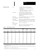
Table
4.4 1336VT Output Current and kV
A
Internal
Chassis
Component Heatsink
Heat Heat Total Minimum
Drive kVA Out kVA Out kVA Out Dissipation Dissipation Dissipation CFM
Amps Out Rating 380V AC 415V AC 460V AC (BTU/hour) n (BTU/hour) n (BTU/hour) n Required n
5.0 B003 3.3 3.6 4.0 119 171 290 15
8.0 B005 5.3 5.8 6.4 154 222 375 20
11.0 B007 7.2 7.9 8.8 239 375 614 32
14.0 B010 9.2 10.1 11.2 290 460 750 40
21.0 B015 13.8 15.1 16.7 409 1040 1449 75
27.0 B020 17.8 19.4 21.5 477 1228 1705 88
34.0 B025 22.4 24.4 27.1 495 1449 1944 100
40.0 B030 26.3 28.8 31.9 597 1620 2217 115
52.0 B040 34.2 37.4 41.4 767 2404 3171 165
65.0 B050 42.8 46.7 51.8 1006 2882 3887 200
77.0 B060 50.7 55.3 61.3 1159 3001 4160 215
96.0 B075 63.2 69.0 76.5 1398 3274 4672 241
124.0 B100 81.6 89.1 98.8 1773 5456 7229 375
156.0 B125 102.7 112.1 124.3 2114 8116 10230 527
180.0 B150 118.5 129.4 143.4 2387 8184 10571 545
240.0 B200 158.0 172.5 191.2 2933 12753 15686 810
300.0 B250 197.4 215.6 239.0 3171 14902 18073 932
n The above information is provided for reference only. For all ratings the user must verify that the selected enclosure will dissipate the total BTUs
generated within the enclosure without allowing the internal ambient to rise above 50°C. Enclosure mounting and location must allow for the heatsink
to extend outside the enclosure.
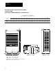
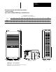
• When locating the drive allow a minimum clearance from other components of 4.0 inches (101.6 mm) on the top and bottom, 2.0 inches (50.8 mm) on
either side.
• When mounting the drive, ensure that the heatsink fins are vertical.
With the heatsink exposed to the ambient, the drive will dissipate heat as listed in the Output Current Table above.