
Manual

Logic Interface Options
Appendix A
A-2
+5V DC+5V DC
100Ω
+5V DC
+5V DC
390Ω
4.7kΩ
390Ω
+5V DC
+5V DC
100Ω
4.7kΩ4.7kΩ
390Ω
100Ω
+5V DC
390Ω
+5V DC
+5V DC
100Ω
4.7kΩ4.7kΩ
390Ω
100Ω
+5V DC
390Ω
+5V DC
100Ω
4.7kΩ4.7kΩ
390Ω
100Ω
+5V DC
390Ω
+5V DC
100Ω
4.7kΩ4.7kΩ
390Ω
100Ω
EARTH
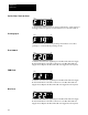
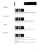
19 20 21 22 23 24 25 26 27 28 29 30
Aux EnableRev SW2 Speed
Select
I
GND
1336MODL1
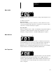
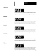
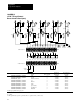
+5V DC TTL Logic Contact
Closure Interface Board (cont.)
3-Wire Control TB3
19 20 21 22 23 24 25 26 27 28 29 30
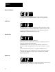
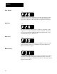
2-Wire Control TB3
Start/Stop
Contact
Start Stop Jog
+5V DC
SW1
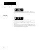
GROUND
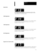
INTERFACE
COMMON
CHASSIS
GROUND
Maximum Recommended
Signal Wire Group ❶ Wire Size ❷ Torque ❸
Terminal 19, Interface Common Start 5 14 AWG 7 In-Lbs
Terminal 20, Interface Common Stop ❹ 5 14 AWG 7 In-Lbs
Terminals 21, 25, 29 Interface Common 5 14 AWG 7 In-Lbs
Terminal 22, Interface Common Jog 5 14 AWG 7 In-Lbs
Terminal 23, Interface Common Reverse 5 14 AWG 7 In-Lbs
Terminal 24, Interface Common SW1 5 14 AWG 7 In-Lbs
Terminal 26, Interface Common SW2 5 14 AWG 7 In-Lbs
Terminal 27, Interface Common Speed Select 5 14 AWG 7 In-Lbs
Terminal 28, Interface Common Auxiliary ❹ 5 14 AWG 7 In-Lbs
Terminal 30, Interface Common Enable ❹ 5 14 AWG 7 In-Lbs
❶
W
ire group number chart, page 6-3.
❷ 2.5mm
2
.
❸ .79N-m.
❹ This signal must be present to permit the drive to operate from any control source.