
Manual

Rockwell Automation Publication DRIVES-IN001M-EN-P - March 2014 63
Best Practices Chapter 4
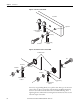
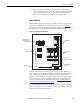
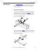
Figure 27 - Multiple Connections to Ground Stud or Bolts
Wire Routing
General
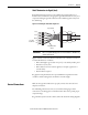
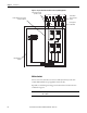
When routing wiring to a drive, separate high voltage power and motor leads
from I/O and signal leads. To maintain separate routes, route these in separate
conduit or use tray dividers.
Category Wiring
Level
Signal Definition Signal Examples Minimum Spacing (in inches) between Levels in Steel
Conduits (cable trays)
Spacing Notes
on page 64
1 2/3/4 5/6 7/8 9/10/11
Power 1 AC power (600V or greater) 2.3kV 3-phase AC lines 0 3 (9) 3 (9) 3 (18) Refer to spacing
note 6
Refer to spacing
notes 1, 2, and 5
2 AC power (less than 600V) 460V 3-phase AC lines 3 (9) 0 3 (6) 3 (12) Refer to spacing
note 6
Refer to spacing
notes 1, 2, and 5
3 AC power AC motor
4 Dynamic brake cables Refer to spacing note 7
Control 5 115V AC/DC logic Relay logic/PLC I/O
motor thermostat
3 (9) 3 (6) 0 3 (9) Refer to spacing
note 6
Refer to spacing
notes 1
, 2, and 5
115V AC power Power supplies,
instruments
6 24V AC/DC logic PLC I/O
Signal
(process)
7 Analog signals, DC supplies Reference/Feedback
signal, 5…24V DC
3 (18) 3 (12) 3 (9) 0 1 (3) Refer to spacing
notes 2, 3, 4, and 5
Digital (low speed) TTK
8 Digital (high speed) I/O, encoder, counter
pulse tach
Signal
(comm)
9 Serial communication RS-232, 422 to
terminals/printers
Refer to spacing note 6
1 (3) 0
11 Serial communication
(greater than 20k total)
ControlNet, DeviceNet,
remote I/O,
Data Highway