
Manual

Rockwell Automation Publication DRIVES-IN001M-EN-P - March 2014 29
Power Distribution Chapter 2
Otherwise, use one of the following more conservative methods:
• For drives without built-in inductors – add line impedance whenever the
transformer kVA is more than 10 times larger than the drive kVA, or the
percent source impedance relative to each drive is less than 0.5%.
• For drives with built-in inductors – add line impedance whenever the
transformer kVA is more than 20 times larger than the drive kVA, or the
percent source impedance relative to each drive is less than 0.25%.
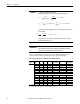
To identify drives with built-in inductors, see the product specific information in
Table 4 on page 30
through Table 13 on page 41. The shaded rows identify
products ratings without built-in inductors.
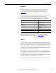
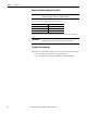
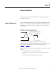
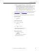
Use these equations to calculate the impedance of the drive and transformer:
Drive Impedance (in ohms)
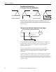
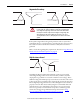
Transformer Impedance (in ohms)
Transformer Impedance (in ohms)
Z
drive
=
V
line-line
3 * I
input-rating
* % Impedance
Z
xfmr
=
V
line-line
3 * I
xfmr-rated
% impedance is the nameplate impedance of the transformer.
Typical values range from 0.03 (3%) to 0.06 (6%).
Z
xfmr
=
(V
line-line
)
2
VA
* % Impedance
or
* % Impedance
Z
xfmr
=
V
line-line
3 * I
xfmr-rated
% impedance is the nameplate impedance of the transformer.
Typical values range from 0.03 (3%) to 0.06 (6%).