
Owner's manual


1336 FORCE-5.19 – August, 2000
Troubleshooting 4-5
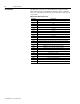
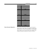
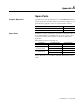
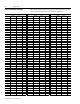
PLC Comm Board Test Points
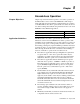
Power Structure Diagnostics After the initial commissioning of the drives, the Power Structure
diagnostics can be run without disconnecting the motor wiring (from
either the Master or Slave). Only one drive (Master or Slave) should
run the diagnostics at a time. To run the diagnostics, set up the Master
drive according to page 3-12 start-up. Issue a start command to only
the Master and check results. Repeat the sequence for the Slave.
Testpoint Application
TP1 DGND
TP2 +5V
TP3 +15V
TP4 AGND
TP5 -15V
TP9 Not Used
TP10 Not Used
TP11 ISO +12 VDC
TP12 ISO -5V
TP13 ISO GND
TP14 IGND
TP15 AIN -1
TP16 AIN -2
TP17 AIN -3
TP18 AIN -3
TP19 AIN -4
TP20 +12V
TP21 AOUT - 2
TP22 AOUT - 3
TP23 AOUT - 4
TP24 +10V REF
TP25 -10V REF