336 FORCE TM Master/Slave Parallel AC Drive 1000 - 1600 HP User Manual Supplement
Important User Information Solid state equipment has operational characteristics differing from those of electromechanical equipment. “Safety Guidelines for the Application, Installation and Maintenance of Solid State Controls” (Publication SGI-1.1 available from your local Allen-Bradley Sales Office or online at http:// www.ab.com/manuals/gi) describes some important differences between solid state equipment and hard-wired electromechanical devices.
Table of Contents Table of Contents Chapter 1 Introduction Manual Objectives ..........................................................................1-1 Who Should Use This Manual.........................................................1-1 System Overview ............................................................................1-1 Drive Configuration..........................................................................1-2 Two Phase Modulation......................................................
ii Table of Contents Nameplate Motor Parameters...................................................3-9 Motor Constants .......................................................................3-9 Torque Regulator......................................................................3-9 Communication Fault/Alarm .....................................................3-9 Uncoupled Motor Checks ................................................................3-9 Power On Tests ......................................
Chapter 1 Introduction Manual Objectives This document is intended as a supplementary addition to the 1336 FORCE 5.12 User Manual. This supplement covers the additional information you will need to install, program, start up and maintain a 1336 FORCE Master/Slave parallel drive combination. Who Should Use This Manual This manual is intended for qualified service personnel who have experience setting up and servicing 1336 FORCE AC Drives.
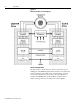
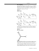
1-2 Introduction Figure 1.1 Master/Slave Drive System Diagram (OPTIONAL) Drive Configuration The master drive controls the motor current, torque and/or speed utilizing the 1336 FORCE patented field-oriented control and model reference adaptive control. The set-up, commissioning, operation, control and communications all operate in the same manner as a standard 1336 FORCE drive. Both the Master and Slave drives’ utilize an analog carrier-based synchronous current regulator. 1336 FORCE-5.
Introduction 1-3 The Slave drive receives the stationary current commands, speed feedback and PWM carrier reference from the Master drive. Each drive maintains its own system-level communication as well as (enable, start, stop and faults). In this application, each inverter regulates its own current, relying on the current regulator to reject the disturbance presented by the other inverter. With sufficiently high PWM carrier (1.5-2.
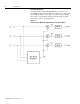
1-4 Introduction Two-Phase Modulation A control feature specific to the Parallel Drive operation is a twophase PWM modulator. The parallel drives change from compensated sine-triangle modulation to two-phase modulation at approximately 65% of drive voltage utilization. This extends the stable operating speed range specific to the parallel drives. Figure 1.3 1336 Two-Phase Modulation Implementation for Parallel Drives 1336 FORCE-5.
Introduction 1-5 Motor Configuration: A custom dual-winding three-phase induction motor is used with the Master/Slave drives. This motor is designed for 0 degrees of phase shift between each of the stator windings (i.e. matched, isolated motor windings in the same slots.). This creates two sets of motor stator windings with a common rotor circuit. Figure 1.
1-6 Introduction The control function on the Master/Slave unit operates in much the same manner as with a standard 1336 FORCE drive. All control functions are performed through the use of parameters that can be changed with a programming terminal or Drive Tools. Feedback information is derived from hardware devices on the process equipment. Feedback and control signals are provided to the drives via the same adapter boards used on Standard FORCE drives.
Introduction 1-7 In parameter 81 (Non-Configurable Fault Status), bit 5 Master/ Slave Cable Loss and bit 6 Master Slave Enable Timeout are specific to the Master/Slave drives. Faults specific to the Master/Slave drives and their probable causes are covered in greater depth in Chapter 4, Troubleshooting. Specifications Specifications for the Master/Slave version of the 1336 FORCE drive match those of standalone units in the the areas of: • Control Specs (see publication1336 FORCE 5.
1-8 Introduction Note: Since each inverter carries 1/2 of the motor load, in cases where each inverter runs at 150% of the inverter rated load, the motor will run at 150% of the motor rating if the motor and inverters have matched ratings. 2 inverters x (150% load) x 1/2 = 150% of Motor Load. • • Output Frequency Range: 0 -150 Hz Efficiency: 97.5% at rated amps, nominal line volts Performance Specifications • Speed Regulation to 0.001% of top speed. • Torque Regulation to +/- 5 % of rated motor torque.
Chapter 2 Mounting and Wiring Your 1336 FORCE Master/Slave Drive Chapter Objectives Chapter 2 provides information so that you can install your 1336T Master/Slave drive.
2-2 Mounting and Wiring Your 1336 FORCE Master/Slave Drive Before Mounting Your Drive Before mounting your drive, consider the following: • what tools and equipment you need to mount your drive • the distance between the motor and the drive • the distance between the drive and other surfaces Mounting The Slave drive is intended to be mounted adjacent to the Master drive. Both the Master and the Slave drive should be located near the converter (common bus supply).
Mounting and Wiring Your 1336 FORCE Master/Slave Drive 2-3 Distance Between the Motor and the Drive Distance requirements for motor cables on a 1336T Drives are the same as with a standard G or H frame FORCE Drive. Follow the recommendations in Chapter 2 and Appendix A of the 1336 FORCE User manual on motor cable size, type and cable termination issues. Grounding Grounding for the 1336 FORCE Master/Slave Drive is primarily the same as for a standard G or H unit.
2-4 Mounting and Wiring Your 1336 FORCE Master/Slave Drive User Enables The hardware user enables (jumper J8 on the PLC Comm Board) must be set identically on both the Master and Slave drives. Set jumper J8 to either 24V or 120V (depending on your application) on both drives. Fault Signals The external fault signals must be interconnected between the master and slave drives. Motor Setup When installing and wiring the motor, the motor connections Must be split between the drives.
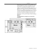
Mounting and Wiring Your 1336 FORCE Master/Slave Drive 2-5 Check the motor connections provided by the vendor. Match motor phasing and motor terminal connections for both the master and slave drives. The Reliance motor shown in the following example matches T1-T11, T2-T22 and T3-T33 for the motor leads. Corresponding customer connections are L1L11, L2 - L22 and L3 - L33.
2-6 Mounting and Wiring Your 1336 FORCE Master/Slave Drive This Page Intentionally Blank 1336 FORCE-5.
Chapter 3 Startup Chapter Objectives Chapter 3 describes the procedure for proper startup and tuning of a 1336 FORCE Master/Slave Parallel Inverter AC drive.
3-2 Startup ! ! Pre-Energization Checks ATTENTION: Working with energized industrial control can be hazardous. Severe injury or death can result from electrical shock, burn, or unintended actuation of controlled equipment. Hazardous voltages may exist in the cabinet even with the circuit breaker in the off position. Multiple sources of power may be connected to this drive.
Startup 3-3 Data Checks- Record motor and drive data and settings in the following checklists. Data Parameter Setting Motor Nameplate Horsepower #228 Hp Motor Base Speed #229 rpm: Motor Rated Current #230 amps: Motor Rated Voltage #231 Volts: Motor Nameplate Frequency #232 Hz: Number of Motor Poles #233 #: Encoder PPR #235 PPR: Rated Inverter Output Amps #220 (Poles = (120xrated freq.) / Sync.
3-4 Startup B. Ground each lead one at a time at motor end and check continuity with a meter at the drive end. This must be done to verify drive output phase connections to ensure no leads are swapped from slave to master. (Severe motor damage will occur if leads are swapped.) C. Connect leads at motor end and megger U (L1 or L11), V (L2 or L22), W (L3 or L33) to ground. Inverter Bridge Checks- Check the inverter bridge for grounds and shorts. A. Measure each incoming phase to ground.
Startup 3-5 Wire Checks - Verify that interconnecting wires to the drive are present, connected and tagged properly. Check particularly: A. E-Coast Stop circuit. B. PLC communications C. That thermalguard wires are used. D. That any options are correctly wired. Power-On Checks If an existing Coast Stop is not available or is not functional, it will be necessary to wire in a temporary Coast Stop pushbutton at TB20-1on the Master Drive PLC Comm Adapter Board.
3-6 Startup Parameter Setup - Drive parameters must be loaded into both the Master and Slave drives before proceeding with further checks and setup routines. Series B 1336T Master/Slave drives must have software version 3.01 or later for both the VP and CP. Load parameters into both drives as you would normally, noting in particular that P220 (Base Drive Curr) and Parameter 221 (Base Line Volt) are Read Only and will be set automatically by each drive upon powerup.
Startup 3-7 P87 (CP Warning/None Configuration Select) = 17 Enable: Bus Ridethrough Timeout and Bus Drop Cycles Warnings. P88 (VP Fault/Warning Configuration Select) = 32823 Enable: Inverter Overload Trip, Motor Stalled, Motor Overload Trip, Motor OverTemperature Tripped, Inverter OverTemp Pending, and Encoder Feedback Loss Faults.
3-8 Startup Parameter 150 (Feedback Device Type) should be set for encoder feedback (P150 = 1) on both the master and slave drive. See Encoderless operation set-up in Chapter 5 for parameter settings specific to encoderless operation. Torque Block Data - Master Drive parameters in the range from 161 to 181 should be set for the process using the settings detailed in the 1336 FORCE user manual. Slave Drive parameters in this range should be set to zero or their minimum value in most cases.
Startup 3-9 Slave Drive - For all versions of CP firmware parameter 227 MUST be set to (0000 0000 1011 1111). This is necessary for correct operation. Different settings may result in improper drive operation. See engineering for different selections. Nameplate Motor Parameters - Motor parameters 228 through 235 should be loaded into BOTH master and slave drive as follows: P228 (motor HP) set to motor rated HP from the nameplate. P229 (motor speed) should be set to base speed from nameplate.
3-10 Startup Uncoupled Motor Checks Power On Tests - When performing tests in the following section, it will be necessary to open two DriveTools screens, for starting and stopping the Master and Slave drives independently. ! ATTENTION: When performing motor checks the following should be observed: 1. Remove all links to the PLC or customer PLC (RIO). 2. Arrange to have representatives from the customer equipped with radio communications watch the powered equipment.
Startup 3-11 The slave drive can be kept in the ready state indefinitely. The master drive enable must be completed within 1 second or the drive will fault. This will decrease the probability that one drive continues operation if the other faults.
3-12 Startup 3. Set P256 = 2 in the Master drive, and give the Master a start command. Motor should start rotating at this point. The motor may sound and feel rough when running below 3 Hz. You may need to increase the phase rotation frequency ref. (P263) to 4 Hz, and phase rotation current ref. (P262) to 75% to get motor rotation. 4. If motor rotation is incorrect, switch two motor leads. Record phase swapping so the slave can be swapped to match the master connections.
Startup 3-13 4. After the motor has reached set speed, using the Drive Enable, disable the drive and measure the decaying motor BEMF as the motor coasts down to zero speed. The phase must be the same on the master and slave motor terminals. If not, rotate phases until they are, and repeat steps 3 and 4. 5. Repeat steps 1 - 4 taking measurements on motor terminal connections T2 to T3 and T22 to T33. 6. Disconnect Master and connect Slave matching any phase changes from Step 4 above.
3-14 Startup Autotune the 1336 Drive ATTENTION: This Autotune sequence is run from the the Master drive only. However both drives require a start signal and will run during autotuning. ! When starting the drive, the Slave MUST be started first, then start the Master drive. (If the Master is started without the Slave running, it will cause an M/S Ena Timeout fault after a 1 second delay. This will require a drive RESET!) When stopping the drive, Stop the Master first, then Stop the Slave.
Startup 3-15 2. Start the Slave Drive followed by starting the Master Drive. The test is complete when P256 resets to zero. 3. Save in EEPROM, the measured value for Leakage Inductance can be viewed in parameter 237 (Lsigma Tune). 4. Repeat test to check validity. Id Measurement Test: 1. Set Parameter 256 [Autotun Diag Sel] to a value of 16. 2. Start the Slave Drive followed by starting the Master Drive. Motor will accelerate toward autotune speed (typically this should occur three separate times).
3-16 Startup Motor Coupled to Mechanical Load Test Prepare the motor for operation by running the following tests: ! ATTENTION: Before you begin this test you MUST confirm the following with the customer to prevent possible machine or motor damage: 1. Motor is coupled to the load. 2. Motor is shimmed and aligned 3. Gearbox and coupling are lubricated 4. Section is lubricated 5. Any required air or water supplies are present 6. Section is ready to run 7.
Startup 3-17 4. Start the Slave Drive followed by starting the Master Drive. 5. The calculated values will appear in Ki (P139), Kp (P140). Save to EEPROM/BRAM. 6. Verify that Parameter 256 (Autotune/Diagnostics Selection) = 0. Application Setup NOTE: Prior to doing any further application specific programming, the application parameters must be programmed for their final value. 1. Start the drive and run up to base speed. If the section is unstable, the drive may have to be retuned.
3-18 Startup 12. Adjust Ki (P139), Kp (P140), and Kf (P141) to obtain desired response. Reduce kf if needed to control overshoots or help achieve stability. Note: P141 (Kf) must equal 65535 for web handling systems that require the drive to accurately track a change in reference or in any section that has an outer loop such as a tension loop. Set the Torque Step Response of the drive as follows: 1. Run the motor RPM up to 1/2 of base speed. a.
Startup 3-19 Filter Setup- In most applications, a fixed light filter (P152 = 1) or a fixed heavy filter (P152=2) will suffice. If needed, a tunable filter can be implemented. 1. To set up a low pass filter: a. Set filter select (P152) to a value of 3 which selects lead/lag. b.Set filter gain (P153) to a value of 0. (Kn = 1 disabled, Kn<1 lag filter, Kn>1 lead filter). c. Set filter bandwidth (P154) to a value greater than or equal to 10 x the bandwidth of the velocity loop, P43. d.
3-20 Startup Special Commands 1336 FORCE-5.
Chapter 4 Troubleshooting Chapter Objectives Chapter 4 provides information specific to troubleshooting the Master/Slave version of the 1336 FORCE drive. Much of the troubleshooting information that pertains to standalone 1336 FORCE drives can be applied to the Master/Slave drive. Refer to the 1336 FORCE user manual (1336 FORCE-5.12) for tests and diagnostic routines that can be applied to the Master/Slave.
4-2 Troubleshooting ◗ ◗ Hand tachometer used to monitor motor velocities. Programming Device Instruction Manual and Adapter Board Reference Manuals. Fault LED’s Two LED’s on the main control board labeled “Master” and “Slave” monitor drive operations. When the Slave Drive is in the ready state, but is not operational the “Slave” LED will blink but the “Enable Slave” LED will be dark.
Troubleshooting 4-3 It is suggested that before attempting a cable replacement, that the main boards be replaced to check the TB12, TB13 connectors. Start with the Main Control board on the Master Drive first and then proceed to the Slave Main Control board before replacing the cable. When replacing the Master/Slave cable, note the orientation of the cable and the number of wraps as it passes thru the ferrite cores at the top of each cabinet.
4-4 Troubleshooting Test Points 1336 FORCE-5.19 – August, 2000 The Hardware testpoints on both the Main Control Board and the PLC Comm Board for both the Master and Slave drives remain the same as for standalone units. The expected output from each testpoint is as follows: Main Control Board Test Points TestPoint Application TP1 DGND TP2 +5V TP3 +15V TP4 AGND TP5 -15V TP6 -2.5 to 2.5V TP7 0 to 2.
Troubleshooting 4-5 PLC Comm Board Test Points Power Structure Diagnostics Testpoint Application TP1 DGND TP2 +5V TP3 +15V TP4 AGND TP5 -15V TP9 Not Used TP10 Not Used TP11 ISO +12 VDC TP12 ISO -5V TP13 ISO GND TP14 IGND TP15 AIN -1 TP16 AIN -2 TP17 AIN -3 TP18 AIN -3 TP19 AIN -4 TP20 +12V TP21 AOUT - 2 TP22 AOUT - 3 TP23 AOUT - 4 TP24 +10V REF TP25 -10V REF After the initial commissioning of the drives, the Power Structure diagnostics can be run without dis
Chapter 5 Encoderless Operation Chapter Objectives Chapter 5 provides information specific to encoderless operation of the Master/Slave version of the 1336 FORCE drive. This chapter deals with application and parameter requirements that are exclusive to the Master/Slave drive when operated in the encoderless mode. For encoderless tuning and troubleshooting information refer to the 1336 FORCE 5.12 User Manual Appendix A. .
5-2 Encoderless Operation ◗ ◗ Parameter Settings 1336 FORCE-5.19 – August, 2000 Torque regulation (+/-5%) is comparable with encoderless and encoder at velocities greater than approximately 25% of base speed. At lower speeds encoderless torque regulation may degrade with changing motor temperature. Torque response is comparable with both encoderless and encoder (200 Hz). Required parameter settings that are unique to Master/Slave Encoderless Operation are: Master Drive: 1.
4-6 Troubleshooting This Page Intentionally Blank 1336 FORCE-5.
Chapter 5 Encoderless Operation Chapter Objectives Chapter 5 provides information specific to encoderless operation of the Master/Slave version of the 1336 FORCE drive. This chapter deals with application and parameter requirements that are exclusive to the Master/Slave drive when operated in the encoderless mode. For encoderless tuning and troubleshooting information refer to the 1336 FORCE 5.12 User Manual Appendix A. .
5-2 Encoderless Operation ◗ ◗ Parameter Settings 1336 FORCE-5.19 – August, 2000 Torque regulation (+/-5%) is comparable with encoderless and encoder at velocities greater than approximately 25% of base speed. At lower speeds encoderless torque regulation may degrade with changing motor temperature. Torque response is comparable with both encoderless and encoder (200 Hz). Required parameter settings that are unique to Master/Slave Encoderless Operation are: Master Drive: 1.
Appendix A Spare Parts Chapter Objectives Appendix A provides the information on 1336 FORCE Master/Slave specific spare parts and a table where user parameter settings for your particular drive application can be recorded for future reference.
A-2 Spare Parts User Parameter Settings The following table should be used to record final parameter settings once you have completed the start up of your application. Drive 1 Param No. Master Setting Drive 2 Slave Setting Notes Param No. Master Setting Drive 3 Slave Setting Notes Param No.
Spare Parts Drive 1 Param No. Master Setting Drive 2 Slave Setting Notes Param No. Master Setting A-3 Drive 3 Slave Setting Notes Param No.
A-4 Spare Parts Drive 1 Param No. Master Setting Drive 2 Slave Setting Notes Param No. Master Setting Drive 3 Slave Setting Notes Param No. 400 400 400 401 401 401 402 402 402 403 403 403 430 430 430 440 440 440 441 441 441 1336 FORCE-5.
Publication 1336 FORCE-5.19 – August, 2000 P/N 304386 (01) Copyright 1999 Rockwell International Corporation. All rights reserved. Printed in USA.