Allen-Bradley 1336 FORCE PLC Communications Adapter (Cat. No.
Important User Information Solid state equipment has operational characteristics differing from those of electromechanical equipment. “Safety Guidelines for the Application, Installation and Maintenance of Solid State Controls” (Publication SGI-1.1) describes some important differences between solid state equipment and hard–wired electromechanical devices.
Table of Contents Preface Manual Overview . . . . . . . . . . . . . . . . . . . . . . . . . . . . . . . . . . . . . Product Overview . . . . . . . . . . . . . . . . . . . . . . . . . . . . . . . . . . . . Terminology . . . . . . . . . . . . . . . . . . . . . . . . . . . . . . . . . . . . . . . . Function Block Components . . . . . . . . . . . . . . . . . . . . . . . . . . . . . Getting Started Chapter 1 Chapter Objectives . . . . . . . . . . . . . . . . . . . . . . . . . . . . . . . . . . .
ii Table of Contents DriveTools’ DriveBlockEditor Download and Compile Operation . . . . Graphic Programming Terminal . . . . . . . . . . . . . . . . . . . . . . . . . . . PLC Block Transfer . . . . . . . . . . . . . . . . . . . . . . . . . . . . . . . . . . . Understanding Multiple Execution List Copies . . . . . . . . . . . . . . . . Task Status Service . . . . . . . . . . . . . . . . . . . . . . . . . . . . . . . . . . . Link Processing Faults . . . . . . . . . . . . . . . . . . . . . . . . . . . . . .
Table Of Contents Program Limits Information: Library Description . . . . . . . . . . . . . . . . . . . . . . . . . . . . . . . . . Scheduled Task Interval (mS) . . . . . . . . . . . . . . . . . . . . . . . . . Maximum Number of Events per Application . . . . . . . . . . . . . . . Number of Function Block Task Files in Product . . . . . . . . . . . . Maximum Number of I/O Nodes Allowed per Application . . . . . . Application Control Commands: BRAM Functions: Store, Recall, and Initialize . . . . . . . . .
iv Table of Contents End of Table of Contents
Preface P–1 Preface Manual Overview This manual attempts to accommodate users who are unfamiliar with the function block system as well as more experienced users. When read from front to back, this manual provides an increasing level of detail, with each chapter building upon information presented in the previous chapter. Chapter 1 is an introductory chapter. It provides general information on the function block system by walking you through a sample application.
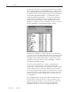
P–2 Preface Shown below are a portion of the function blocks that are available viewed through DriveTools DriveBlockEditor. By scrolling forward, the 28 different function blocks that currently make up the function block library may be viewed. Functions range from logical function blocks (AND, OR, XOR and NOT) — to math function blocks (ADD, SUB, MULT and SCALE) — to more involved functions, including Proportional/Integral Control and Rate Limiter.
Preface Terminology P–3 Application — An application is represented by an event list and it’s associated function, nodes and links. Block Type Number — The block type number specifies one of the 28 different types of function blocks currently installed in the function block library. You can use each type of function block as many times as required in an execution list. Block ID# — A block ID# is a unique number assigned to a function block when it is entered into an execution list.
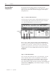
P–4 Preface Function Block Components Developing and successfully entering a new function block application in your 1336FORCE involves four distinct steps. These steps are shown below and on the following pages of this chapter using DriveTools. Step 1 — Create an Execution List. You can create an execution list by entering function blocks into an on screen display. The execution list entries are shown on the left side of the DriveBlockEditor screen shown below.
Preface P–5 Limit Node Group Value Entries Link Entries Step 3 — Enter Links You can now use links to alter an application by connecting function block inputs and outputs to other nodes or linear parameters in the drive. Links are accomplished by entering block ID’s and nodes in the Link To column on the right side of the DriveBlockEditor screen. In the example shown below, Rate Limit output node 5 (4:5) is linked to Limit Block node 0 (1:0).
P–6 Preface End of Preface 1336 FORCE – 5.
Chapter 1 1–1 Getting Started Chapter Objectives Min Value (–32765) LIMIT ID # 1 Out1 Set Max Lim Input 1 Max Value (+32765) This chapter introduces you to an application using function block programming. The exercises in this chapter take you through the programming of the sawtooth generator application shown below.
1–2 Getting Started Sawtooth Application Operation The output from the RATE LIMITER function block will be a sawtooth signal. The value of the RATE LIMITER output will ramp up to the value specified by the MULTIPLEXER input #1 (+32767). When the RATE LIMITER output reaches the maximum value specified by the LIMIT block t1 (+32765), the max limit flag will set the SR FLIP FLOP output, which in turn selects the MULTIPLEXER input #2. The RATE LIMITER output will then ramp down to this new value of – 32767.
Getting Started Getting Started Using DriveBlockEditor 1–3 To start DriveTools: ❒ Enter DriveTools. ❒ Select DriveBlockEditor. ❒ Select the New option from the DriveBlockEditor’s pull-down File menu to create a new execution list. The display shows a function block library list similar to the one shown on the next page. ❒ Select the file. ❒ Click on OK. 1336 FORCE — 5.
1–4 Getting Started Step 1 — Add a Limit Block 1. Select the Add Block option from the Function Blocks pull-down menu. 2. Double click on Limit — [Lib ID: 12]. ❒ Click on CLOSE. As shown below, the DriveBlockEditor software now enters one Limit function block in your new execution list with an ID# of 1. 3. Enter the maximum value by clicking on the Value field for Node 1 and entering +32765. Press enter to save the value as shown below. 1336 FORCE — 5.
Getting Started 1–5 4. Enter the minimum value by clicking on the Value field for Node 2 and entering –32765. Press enter to save the value as shown above. You have now created the first function block and set the input node value limits as shown below. NODE# BLOCK ID# Input 1 1:0 @ Max Lim 1:3 LIMIT @ Min Lim 1:4 Max Val (32765) 1:1 Min Val (–32765) 1:2 Output 1:5 ID # 1 Step 2 — Enter a Set/Reset FF Block To add a Set Reset FF function block: 1.
1–6 Getting Started You can now link the Set Reset Flip Flop inputs to the outputs of the Limit function block entered in Step 1. 5. Link the Set Reset FF’s set input (node 0), to the maximum limit flag of the Limit function block (node 3). Click on the Link To field for Node 0 and enter 1:3. Press enter to save the value as shown below. 6. Link the Set Reset FF’s reset input (node 1), to the minimum limit flag of the Limit function block (node 4). Click on the Link To field for Node 1 and enter 1:4.
Getting Started 1–7 Step 3 — Enter a Multiplexer Block To add a Multiplexer function block: 1. Move the cursor to the left side of the execution list and click. 2. Select the Add Block option from the Function Blocks pull-down menu. 3. Double click on Multiplexer — [Lib ID: 21]. 4. Click on CLOSE. As shown below, the DriveBlockEditor software now enters a Multiplexer function block and gives it an ID # of 3. 5. Enter a value for input 1 by clicking on the Value field for Node 0 and entering +32767.
1–8 Getting Started 7. Link the Multiplexer’s sel0 input (node 4), to the Set Reset FF’s output (node 2). Click on the Link To field for Node 4 and enter 2:2. Press enter to save the value as shown below. With the Multiplexer function block values and link added, the function block diagram now appears like this.
Getting Started 1–9 Step 4 — Enter a Rate Limit Block To add a Rate Limit function block: 1. Move the cursor to the left side of the execution list and click. 2. Select the Add Block option from the Function Blocks pull-down menu. 3. Double click on Rate Limiter — [Lib ID: 19]. 4. Click on CLOSE. As shown below, the DriveBlockEditor software now enters a Rate Limiter function block and gives it an ID # of 4. 5. Enter a value for the rate by clicking in the Value field for Node 3 and entering 65535.
1–10 Getting Started Press the enter key to save the value as shown below. Step 5 — Modify the Limit Block 1. Move to the Limit function block node entry field by clicking on ID # 1. Link the Limit’s input (node 0), to the Rate Limiter’s output (node 5). Click on the Link To field for Node 0 and enter 4:5. Press the enter key to save the value as shown below. The block diagram is now complete and should appear as shown below with the Rate Limiter function block added.
Getting Started 1–11 Step 6 — Check Links Once all function blocks and their links have been established, node connections in the program should be validated by using a Check Node Connections command from the Function Blocks pull-down menu. This function is performed by the DriveBlockEditor, not the drive. If all links are correct, the following display will be shown. If any errors were made, a Connection Errors Dialog Box will detail the errors.
1–12 Getting Started 3. Upon completion, select the Connect to Drive option from the DriveBlockEditor’s pull-down Drive menu and re-enter the station number to go online. 4. Once online, verify that values are changing at the Rate Limiter function block’s output node. Step 8 — Link Analog Output Parameters to Function Block Nodes Enter the DriveManager program to link linear parameters. 1. Enter a scale factor value of 2048 for Parameters 401 and 405.
Getting Started 1–13 2. Enter an offset value of 0 for Parameters 400 and 404. This allows a value of ±32767 to traverse the entire ±10V range for both analog outputs. 3. Within the link window at the bottom of the screen, double click on the Par # field associated with Parameter 387. Link analog output #1, Parameter 387, to Rate Limiter output node Output (4:5). The window shown below should appear with entry boxes. 4. Enter a Task Number of 1. Enter a Block Number of 4. Enter a Node Number of 5.
1–14 Getting Started 5. Double click on the Par # field associated with Parameter 389. The window shown below should appear with entry boxes. 6. Enter a Task Number of 1. Enter a Block Number of 4. Enter a Node Number of 0. Click on OK. If desired, you can now use DriveMonitor or an oscilloscope to view the analog outputs in a graphic format. Important: DriveMonitor can be used to monitor any function block node directly.
Getting Started Getting Started Using a PLC 1–15 Shown below is a sample program that will transfer data to a drive that is set up as Rack 1. The block transfers are executed by toggling input I:00/00. The Block Transfer Write sends the information in data file N57:0 to the drive. The data in these addresses determines what type of operation is performed. The Block Transfer Read instruction receives information from the drive and places it in data file N57:100.
1–16 Getting Started Step 1 — Initialize the Function Blocks Initialize the function block BRAM to clear the current function block application. 1. Toggle bit I:00/00 to indicate the block transfer. 2. Verify that the initialization was successful. 3. If N57:101 = 0F02 hex (Block Transfer Read Data), there are no errors. BTW Data File N57:0 0 1 2 3 4 5 6 7 8 9 0000 8F02 0000 0003 0000 0000 0000 0000 0000 0000 Words N57:0 – N57:3 will be sent to the drive.
Getting Started 1–17 Step 3 — Write Node Values One node value is downloaded in each block transfer routine. The same block transfer routine is used in each download, but information in the data file is changed for each node value that is transferred. As shown below, the data in word N57:2 specifies the block and node that is being written to, while word N57:3 specifies the value that is being sent. Data is entered in hexadecimal format.
1–18 Getting Started — Enter the 3rd Value at the Function Block Node BTW Data File N57:0 0 1 2 3 4 5 6 7 8 9 0000 8F01 8003 7FFF 0 0 0 0 0 0 7. Set the Multiplexer block Input 1 value (block 3, node 0) to 7FFFhex = 32767dec. 8. Toggle bit I:00/00 to initiate the block transfer routine which downloads the node value. 9. Verify that the write was successful. If N57:101 = 0F01 hex (Block Transfer Read data), there are no errors.
Getting Started 1–19 Step 4 — Write Links One node link is downloaded in each block transfer routine. The same block transfer routine is used in each download, but information in the data file is changed for each node link that is transferred. The data in word N57:2 specifies the block and node that receives the data, while word N57:3 specifies the block and node that provides the data. Data is entered in hexadecimal format.
1–20 Getting Started — Link the SR FF Block Reset to the Limit Min Limit Flag BTW Data File N57:0 0 1 2 3 4 5 6 7 8 9 0000 8F04 8102 8401 0 0 0 0 0 0 7. Link the SR FF block Reset (block 2, node 1) to the Limit Min Limit Flag (block 1, node 4). 8. Toggle bit I:00/00 to initiate the block transfer routine which will download the link. 9. Verify that the write was successful. If N57:101 = 0F04 hex (Block Transfer Read data), there are no errors.
Getting Started 1–21 Step 5 — View Node Values Drive analog outputs can be linked to function block nodes. Analog scale factors can be set and the analog outputs can be linked to the function block nodes by using the same block transfer routine. A device such as an oscilloscope can be connected to the analog outputs to monitor the operation of the function block program.
1–22 Getting Started — Link Analog Output 1 to the Rate Limit Output BTW Data File N57:0 0 1 2 3 4 5 6 7 8 9 4 8900 183 8504 0 0 0 0 0 0 1. Link Analog Output 1 (Parameter 387) to the Rate Limit output (Block 4, Node 5). 2. Toggle bit I:00/00 to initiate the block transfer routine which processes all function block links. 3. Verify that the write was successful. If N57:101 = 0900 hex (Block Transfer Read data), there are no errors.
Chapter 2 2–1 System Component Detail Chapter Objectives This chapter provides information about the following system component concepts: ❒ ❒ ❒ ❒ Execution List Overview Execution lists and their events Downloading and compiling function block applications Understanding function block I/O nodes Connecting or linking blocks An execution list provides a way for you to organize the function blocks, or events, in the order that you want the drive to execute the events.
2–2 System Component Detail When you use DriveTools, block names are displayed in place of block type numbers. Basically, a block name uses words to identify the block type. Therefore, the block name always corresponds to the same block type number. DriveTools shows the execution order number in the left column. The following is an example execution list from the DriveTools’ DriveBlockEditor. Event values are easier to understand when they are represented by a hexadecimal value.
System Component Detail 2–3 Within the drive, the execution list is stored as an array of words.
2–4 System Component Detail Creating an Execution List The steps needed to create an execution list vary depending on the type of terminal you are using. You should refer to the appropriate documentation for information specific to your terminal. However, general steps for creating an execution list are included here. ❒ If you are using the DriveTools software, you can create an execution list offline by selecting the New option from the DriveBlockEditor’s pull–down File menu.
System Component Detail Important: 2–5 If you insert a NO-OP event when using the DriveTools’ DriveBlockEditor, the DriveBlockEditor appears to assign an ID number to a NO-OP event block when added to an off–line file. However, the ID number is not sent to the drive during download for NO-OP blocks. When an on–line file is uploaded, all NO–OP blocks have an ID number of 0.
2–6 System Component Detail For example, if you want to use the output, or result, of an ADD2 function block as an input to a SCALE function block, you can create a link between the two function blocks as shown here. Input ADD2 Output Input SCALE Output Link between nodes You can also create a function block that is linked to a linear parameter, such as the velocity feedback parameter.
System Component Detail 2–7 If you want both function blocks to receive the same value for a drive parameter, you should link the first function block’s input node to the drive parameter. You should link all subsequent inputs using this drive parameter should be linked to the first function block node that is linked to the drive parameter. In this second example, you want the MULTIPLY function block to receive the same value from the drive parameter as the LIMIT function block.
2–8 System Component Detail Downloading and Compiling the Execution List While you are creating your execution list, you are generally working on a terminal using DriveTools, a PLC, or a GPT. At this point, the execution list is an array of words that the software you are using can understand. You need to download and compile your execution list before the drive can execute it. The download process sends a copy of the execution list array from the terminal to the drive.
System Component Detail Understanding Function Block I/O Nodes 2–9 Once you have properly downloaded and compiled your execution list, you can access the I/O (input/output) nodes associated with each function block. An I/O node is a parameter that provides information to or from a function block. The function block I/O nodes are different from the standard linear parameters. While the linear parameters always reference the same information, the I/O nodes are dynamic.
2–10 System Component Detail DriveBlockEditor Node References If you are using DriveTools, you can reference a specific node of a particular function block by specifying the block ID:node number. For example, to reference block number 6, node 2, you would enter 6:2. Even though the DriveTools’ DriveBlockEditor allows you to reference I/O nodes as block ID:node number, the DriveBlockEditor software converts the decimal information into the single word reference number.
System Component Detail 2–11 Examples of Function Block I/O Node References The first example represents output node 2 of an ADD function block that has a block ID of 6. You can convert this information to either a decimal value or a hexadecimal value.
2–12 System Component Detail Node Data Types The value of a function block I/O node will be one of the following types: ❒ A signed decimal integer with a value range of ±32767. ❒ An unsigned decimal integer with a value range of 0 – 65535. ❒ A logical value where 0 = False and any non-zero value = True. Some nodes have additional range restrictions. For example, a node may be a signed integer with a range of ±16383 instead of ±32767. In addition, nodes may be linkable or non–linkable.
System Component Detail 2–13 Creating Links Between Nodes When you create a link between two function blocks, you are actually creating a connection between a node on one function block and a node on another function block. The information about the link is stored at the destination node, which is the node that receives the data.
2–14 System Component Detail If you are using a PLC, you would create this same link by doing the following: 1. Set up your block transfer read and write blocks. 2. Create your data table. For this example, your data table would look like the following: BTW Data File N10:10 0 1 2 3 0 8F04 8002 8301 Write Link Service Request Destination Node 4 5 6 7 8 9 Source Node The 8002 in column 2 specifies that Node 0 of Block ID 2 (the Set Reset FF function block) is receiving information.
Chapter 3 3–1 System Interactions Chapter Objectives This chapter provides information about the following topics: ❒ ❒ ❒ ❒ ❒ ❒ ❒ The Function Block BRAM Functions The function block BRAM functions The power up sequence The compiler modes and terminal operation differences Multiple execution list copies The task status services The link processing faults The performance issues that concern links Function block applications use two kinds of memory: RAM and BRAM.
3–2 System Interactions The Function Block Init Command A function block Init operation effectively removes any previous function block application from the working RAM area. However, it does not actually clear out the BRAM itself; it only clears the function block application out of the working RAM area. To truly initialize the BRAM area, you need to perform both an initialization service and a function block Store operation. When requested, a function block Init does the following: 1.
System Interactions The Function Block Recall Command 3–3 A function block Recall copies the function block application that is currently stored in BRAM into RAM. This application is then stored in RAM and is available for execution. When requested, a function block Recall does the following: 1. Verifies the function block data checksum before performing a function block RAM initialization. 2.
3–4 System Interactions For example, if your RAM area is as shown below, a linear parameter BRAM Init would clear links A and B, while a function block BRAM Init would clear all function blocks as well as links B, C, and D. Drive Parameters P#01 P#02 P#03 . .. P#298 P#299 P#300 Adaptor Parameters D A P#301 P#302 P#303 Links A and B are made using DriveManager or linear parameter Block Transfer services.
System Interactions 3–5 If you do a Recall on the linear parameter area before doing a Recall on the function block area, no function blocks will exist in RAM. When the linear parameter Recall is executed, it cannot build link B because the function block that provides the data to the linear parameters does not yet exist in RAM. This will cause a drive soft fault to occur. The system does not automatically clear a link that was valid but has become invalid.
3–6 System Interactions Compiler Modes and Terminal Operation Differences You can use any of the three supported terminal devices to create and update your function block applications: ❒ DriveTools’ DriveBlockEditor ❒ Graphic Programming Terminal (or GPT) ❒ PLC block transfer The three terminal devices use different compiler modes due to differences in the amount of their available RAM.
System Interactions 3–7 Subsequent Compile Mode With the subsequent compile mode, a new execution list is compared against the current application in the drive to selectively create and delete function block objects. This compile mode is automatically enabled when a previously valid application exists in the drive. Common event blocks will retain previous node values and links. Only the new event blocks need to be adjusted. The GPT uses the subsequent compile mode for its download and compile service.
3–8 System Interactions The following example is not valid because block ID 23 was re–used for a new event when it was already assigned to a BIN2DEC function block. Existing, valid application Exec# Block ID 1 21 2 22 3 23 4 24 5 25 6 26 Block Type ABS AND4 BIN2DEC COMPHY DEC2BIN DELAY New (subsequent) event list Exec# Block Block Type ID 1 21 ABS 2 22 AND4 3 23 Integral 4 24 COMPHY 5 25 DEC2BIN 6 26 DELAY In this last example, the second execution list is invalid only in the subsequent compile mode.
System Interactions 3–9 During a download operation, the DriveTools’ DriveBlockEditor does the following: 1. Performs a function block Init which effectively removes the function block application from the system. This initialization goes over the linear parameter link reference table and clears any links to function block source nodes. These links are not rebuilt until you make a call to the linear parameter Recall function.
3–10 System Interactions Understanding Multiple Execution List Copies Only one function block application is active within the drive at any one time. However, multiple execution lists can be present in the terminal devices attached to the drive. You can connect up to seven terminal devices to the PLC Communications Adapter board, and each terminal device can have its own copy of an execution list.
System Interactions Task Status Service 3–11 The compile operation performed during the function block Recall and the download and compile services are performed as background tasks. Even though you can perform other service requests while the execution list is compiling, you should avoid making node value write requests and link requests during the compilation process. You can use the Task Status service to determine the current state of the compiler and the application execution status.
3–12 System Interactions Link Processing Faults A link processing error is indicat
System Interactions Performance Issues Involving Links 3–13 A drive with a connected PLC Communication Board has two link processing mechanisms. One link processing mechanism operates specifically upon linear parameter links, and the other mechanism processes the function block links. As the application executes, the function block links are processed block by block. The inputs for each individual block are checked for links.
3–14 System Interactions To make nodes linked to a common linear parameter operate upon the same value every 20 milliseconds, you can link the input of the second event to the input of the first event. As shown here, you could link the input of event 115 to the input of event 1. Feedback from the drive Input T1 LIMIT Event 1 T2 Input MULTIPLY Event 115 T1 in this example represents the first transfer of data, and T2 represents the second transfer of data.
Chapter 4 4–1 Function Block Library Chapter Objectives Detailed in this chapter are the (28) function blocks that make up the PLC Comm Board function block set. Function Block Overview Each function block is a firmware subroutine stored in PLC Comm Board Memory. Each type of function block has a unique Block type number that identifies the functionality and the nodes that are associated with the block.
4–2 Function Block Library Double Word Function Block Caution The only library function blocks that have double word input or output nodes are Multiply, Divide and Scale. These three function blocks are intended to be used together. Special handling may be required when using any of these three blocks with other function blocks. Double word nodes can present difficulties since the system architecture does not have 32 bit integrity.
Function Block Library 4–3 Function Block Index FUNCTION BLOCK TYPE DESCRIPTION PAGE ABS 1 An absolute value function block whose output is the positive value. 4–4 BIN2DEC 3 A binary to decimal function block that takes (16) input words and produces (1) decimal output word. 4–5 COMPHYST 4 Compare with hysteresis function block that checks for input = preset value with a hysteresis around the value.
4–4 Function Block Library ABS BLOCK TYPE 1 decimal 1 hexadecimal NODE 0 Absolute ID = Input Exec = IN Out NODE 1 DEFINITION An absolute (+) output value Out derived from a 16-bit signed (+ or –) 2’s complement input Input. INPUT Input — A signed Integer. OUTPUT Out — An unsigned integer that is the absolute value of Input. FUNCTION Out = |Input|. 1336 FORCE — 5.
Function Block Library BIN2DEC BLOCK TYPE 3 decimal 3 hexadecimal NODE 0 NODE 1 NODE 2 NODE 3 NODE 4 NODE 5 NODE 6 NODE 7 NODE 8 NODE 9 NODE 10 NODE 11 NODE 12 NODE 13 NODE 14 NODE 15 Binary to Dec ID = Exec = In Bit 0 In Bit 1 In Bit 2 In Bit 3 In Bit 4 In Bit 5 In Bit 6 In Bit 7 In Bit 8 In Bit 9 In Bit 10 In Bit 11 In Bit 12 In Bit 13 In Bit 14 Output In Bit 15 4–5 DEC BIN NODE 16 DEFINITION Combines 16 logical input words In Bit 0 – In Bit 15 into 1 decimal output word Output.
4–6 Function Block Library BIN2DEC (continued) EXAMPLES EXAMPLE 1 Example 2 EXAMPLE 3 In Bit 0 In Bit 1 False True False True False True In Bit 2 In Bit 3 False False False False False True In Bit 4 In Bit 5 False False False False False True In Bit 6 In Bit 7 False False False False True True In Bit 8 In Bit 9 False False False True True True In Bit 10 In Bit 11 False False False False True True In Bit 12 In Bit 13 False False False False True True In Bit 14 In Bit 15 Fa
Function Block Library COMPHYST BLOCK TYPE 4 decimal 4 hexadecimal NODE 0 NODE 1 NODE 2 4–7 Compare w/Hyst ID = Exec = In1 Pre Hyst EQ LT GT NODE 3 NODE 4 NODE 5 DEFINITION Compares the input value In1 against a preset value Pre with an associated hysteresis band Hyst and sets the appropriate indicator flags. EQ Output FALSE PRE (–) HYST TRUE FALSE PRESET PRE (+) HYST INPUTS In1 — Input value signed integer. Pre — Preset value signed integer.
4–8 Function Block Library COMPHYST (continued) 1336 FORCE — 5.
Function Block Library DEC2BIN BLOCK TYPE 5 decimal 5 hexadecimal NODE 0 Dec to Binary ID = Exec = Out Bit 0 Input Out Bit 1 Out Bit 2 Out Bit 3 Out Bit 4 Out Bit 5 Out Bit 6 Out Bit 7 Out Bit 8 Out Bit 9 Out Bit 10 Out Bit 11 Out Bit 12 Out Bit 13 Out Bit 14 Out Bit 15 DEC BIN 4–9 NODE 1 NODE 2 NODE 3 NODE 4 NODE 5 NODE 6 NODE 7 NODE 8 NODE 9 NODE 10 NODE 11 NODE 12 NODE 13 NODE 14 NODE 15 NODE 16 DEFINITION Takes 1 unsigned decimal input word Input and produces 16 logical output words Out Bit 0 to
4–10 Function Block Library DEC2BIN (continued) EXAMPLES Example 1 EXAMPLE 2 Input Out Bit 0 14 False 65584 False Out Bit 1 Out Bit 2 True True False False Out Bit 3 Out Bit 4 True False False True Out Bit 5 Out Bit 6 False False True False Out Bit 7 Out Bit 8 False False False False Out Bit 9 Out Bit 10 False False False False Out Bit 11 Out Bit 12 False False False False Out Bit 13 Out Bit 14 False False False False Out Bit 15 False True Example 1 — Input = 14 dec = 000E h
Function Block Library DELAY BLOCK TYPE 6 decimal 6 hexadecimal NODE 0 NODE 1 NODE 2 NODE 3 Delay ID = Input Enable On (ms) Off ms. 4–11 Exec = OUT IN Out Out Not NODE 4 NODE 5 DEFINITION The output echoes the logical input after a specified time delay. Separate time delays of On (ms) and Off ms. are provided for rising and falling edges. The resolution of the on and off delay times are calculated and limited by the 20mS task interval. INPUTS Input — A logic input.
4–12 Function Block Library DELAY (continued) PARAMETERS DATA TYPE LINKABLE DEFAULT VALUE RANGE Input Enable Logic Input Logic Input Yes Yes 0 0 True/False True/False On (ms) Off ms.
Function Block Library Derivative ID = Exec = In DERIV BLOCK TYPE 7 decimal 7 hexadecimal 4–13 NODE 0 IN t Out NODE 1 DEFINITION The rate of change of input In over a single sample interval. Τhe sample interval ∆t = .020 seconds. Output Out is clamped at ±32767 and not allowed to over or under flow. INPUT In — A signed Integer. OUTPUT Out — A signed integer representing the derivative or change in input in units per second. FUNCTION Out = 50 × [In — In (previous)].
4–14 Function Block Library DERIV Example 2 — Rate = 16383 Units-per-Second (UPS) (continued) + 16383 DERIV Out 0 – 16383 Ramp Input Rate = + 16383 UPS – 32767 In the example above, the rate limit input to the derivative function is set to allow a 16383 UPS change of output. A constant rate-of-change to the input, yields a constant output level of ± 16383, with the output sign changing with the input slope. 1336 FORCE — 5.
Function Block Library DIVIDE BLOCK TYPE 23 decimal 17 hexadecimal NODE 0 NODE 1 NODE 2 Divide ID = LSW In MSW In Div 4–15 Exec = Output NODE 3 DEFINITION Divides a 32 bit signed integer by a 16 bit signed integer. Any remainder is truncated. If Div = 0, the calculation is not performed and Output = 0. The Output is clamped to ±32767 should the result exceed the limits. INPUTS LSW In — A least significant dividend word value representing bits 0–15 of a 32 bit dividend value.
4–16 Function Block Library DIVIDE DOUBLE WORD VALUES (continued) Both the Most Significant Word and the Least Significant Word are interpreted together by the function algorithm as one word when using 32 bit values. The range of a double word value is ±2,147,483,647. The range of the more common, signed single-word 16 bit node is ±32767. Most Significant Word Least Significant Word 16 15 31 Node 1 0 Node 0 Bit 31 is the sign bit, the most significant bit for 32 bit values.
Function Block Library DIVIDE Important: (continued) 4–17 If the DIVIDE function block’s LSW input node (node 0) is used without manipulating the MSW node (node 1), difficulties can occur should a signed word be linked to the inputs. False results may be output if the signed input value goes negative.
4–18 Function Block Library EXOR2 BLOCK TYPE 25 decimal 19 hexadecimal NODE 0 NODE 1 Exclusive OR ID = Exec = In #1 In #2 Out #1 Out #2 NODE 2 NODE 3 DEFINITION An exclusive OR function that takes (2) inputs In #1 and In #2,. and provides the XOR and XNOR — Out #1 and Out #2. INPUTS In #1 — A logical input value. In #2 — A logical input value. OUTPUTS Out #1 — A logical output value. Out #2 — A logical output value.
Function Block Library FILTER BLOCK TYPE 8 decimal 8 hexadecimal NODE 0 NODE 1 Filter ID = In Rad /S 4–19 Exec = Out NODE 2 DEFINITION A first order low pass algorithmic filter with a programmable bandwidth in increments of .1 radians/second. INPUTS In — The signed integer to be filtered. Rad/S — The bandwidth in .1 radians/second, with a maximum value of 400 (40 radians). OUTPUT Out — A signed, filtered, output integer that is clamped to ±32767. FUNCTION If Rad/S = 0, then Out = In.
4–20 Function Block Library FILTER Example 2 — (2) Radians-per-Second — Horizontal Scale = 500 mS/Division (continued) " 1 Time A Constant ≈ 63% ≈ 500 mS + 32767 " FILTER In " A FILTER Out – 32767 " A––– 3 Time Constants –––" ≈ 96% ≈ 1.5 S Example 3 — (1) Radian-per-Second — Horizontal Scale = 500 mS/Division + 32767 " FILTER Out " A FILTER In – 32767 " A–– 1 Time –––" Constant ≈ 63% ≈ 1 S A–––––––––– 3 Time Constants ≈ 96% ≈ 3 S ––––––––––" 1336 FORCE — 5.
Function Block Library 4AND BLOCK TYPE 2 decimal 2 hexadecimal NODE 0 NODE 1 NODE 2 NODE 3 4–21 Four Input And ID = Exec = Input #1 Input #2 Input #3 Input #4 Out 1 Out 2 NODE 4 NODE 5 DEFINITION Performs a logic AND and NAND of Input #1, Input #2, Input #3, and Input #4. INPUTS Input #1 Input #2 Input #3 Input #4 — — — — A logic input value. A logic input value. A logic input value. A logic input value. OUTPUTS Out 1 — A logic output value. Out 2 — A logic output value.
4–22 Function Block Library 4OR BLOCK TYPE 16 decimal 10 hexadecimal NODE 0 NODE 1 NODE 2 NODE 3 Four Input OR ID = Exec = Input #1 Input #2 Input #3 Input #4 Out #1 Out #2 NODE 4 NODE 5 DEFINITION Performs a logic OR and NOR on four input words. INPUTS Input #1 Input #2 Input #3 Input #4 — — — — A logic input value. A logic input value. A logic input value. A logic input value. OUTPUTS Out #1 — A logic output value. Out #2 — A logic output value.
Function Block Library FUNCTION BLOCK TYPE 9 decimal 9 hexadecimal NODE 0 NODE 1 NODE 2 NODE 3 NODE 4 NODE 5 NODE 6 NODE 7 Function ID = Input Smp Val1 Smp Val2 Smp Val3 Smp Val4 Smp Val5 Min Val Max Val 4–23 Exec = @Min Lim @Max Lim Output NODE 8 NODE 9 NODE 10 DEFINITION A function generator that uses: ❒ Sample values Smp Val1—Smp Val5 to define the y-axis components. ❒ (2) signed integers Min Val & Max Val to describe the x-axis components spaced in (Max Val—Min Val)/4 increments.
4–24 Function Block Library FUNCTION 3. If Min Val < Input and < Max Val: Calculate xi, xi+1 from Input, where xi ≤ Input ≤ xi+1. Calculate yi, yi+1 from xi, xi+1. Output = { [(yi+1 – yi ) × (Input – xi)] / (xi+1 – xi) } + yi @Max Lim = @Min Lim = false.
Function Block Library FUNCTION 4–25 Example 3 (continued) Smp Val2 B + 32767 " FUNCTION Output B + 16383 " Y Smp Val1 Smp Val4 B Y Smp Val3 – 16383 " Y Smp Val5 FUNCTION Input B – 32767 " Example 4 + 32767 " FUNCTION Output B Smp Val2 B Y Smp Val1 A Smp Val4 Y Smp Val3 FUNCTION Input B Y Smp Val5 – 32767 " 1336 FORCE — 5.
4–26 Function Block Library INTEGRATOR BLOCK TYPE 10 decimal 0A hexadecimal NODE 0 NODE 1 NODE 2 NODE 3 NODE 4 NODE 5 Integrator ID = Input Set Preset Gain Min Max Exec = t Lo Lim Hi Lim Output NODE 6 NODE 7 NODE 8 DEFINITION Integrates an input value Input over a period of time using trapezoidal integration. The Output is limited to Min and Max values that are defined by the user. The integrator can be set to the Preset value when the Set input is true.
Function Block Library INTEGRATOR 4–27 FUNCTION Denominator = 1/2 × ∆t × 1/(divisor gain) = 25600 where: ∆t = a task interval of .020 seconds = 1/50 samples/second. divisor gain = 256. 1. If Set = true, accumulator = Preset × denominator. 2. If Set = false, accumulator = [Gain × (Inputi–1 + Input)] + previous accumulated value. 3. If accumulator ÷ denominator > Max, Output = Max, Hi Lim = true, Lo Lim = false. 4. If accumulator ÷ denominator < Min, Output = Min, Hi Lim = false, Lo Lim = true. 5.
4–28 Function Block Library Example 2 — Gain = 512 = 2 × — Horizontal Scale = 500 mS/Division INTEGRATOR (continued) + 32767 " + 16383 " INTEGRATOR Input B – 16383 " – 32767 " Y INTEGRATOR Output In Example 2, the Output also changes at a rate of 32767 units-per-second. The Input level here is only 16383, but input Gain has doubled.
Function Block Library INTEGRATOR 4–29 Example 4 — Preset Verification — Preset = 0 — Horizontal Scale = 500 mS/Division (continued) + 32767 " INTEGRATOR Set Input B + 16383 " – 16383 " – 32767 " Y INTEGRATOR Output Example 4 demonstrates the Preset functionality. When the Set input is raised the Output is preset to a value of zero. When the Set node is cleared, the integral begins accumulating from the Preset value, 0. 1336 FORCE — 5.
4–30 Function Block Library LIMIT BLOCK TYPE 12 decimal 0C hexadecimal NODE 0 NODE 1 NODE 2 Limit ID = Input 1 Max Val Min Val Exec = Max Lim Min Lim Output NODE 3 NODE 4 NODE 5 DEFINITION Limits an input Input 1 to the programmed maximum Max Val and minimum Min Val values. INPUTS Input 1 — A signed integer that is limited. Max Val — A signed integer that represents a maximum input value. Min Val — A signed integer that represents a minimum input value.
Function Block Library LNOT BLOCK TYPE 15 decimal 0F hexadecimal NODE 0 4–31 Logical NOT ID = Exec = Input Output NODE 1 DEFINITION Performs a logic inversion of the Input. INPUT Input — A logic input value. OUTPUT Output — A logic output value. FUNCTION Output = (Not)Input. PARAMETERS DATA TYPE LINKABLE DEFAULT VALUE RANGE Input Output Logic Input Logic Output Yes No False — True/False True/False EXAMPLES EXAMPLE 1 EXAMPLE 2 Input False True Output True False 1336 FORCE — 5.
4–32 Function Block Library MINMAX BLOCK TYPE 13 decimal 0D hexadecimal NODE 0 NODE 1 NODE 2 Min/Max ID = In #1 In #2 Select Exec = Output NODE 3 DEFINITION Chooses the minimum or maximum of two input values In #1, In #2 according to the Select Input. INPUTS In #1 — A signed integer that is compared to In #2. In #2 — A signed integer that is compared to In #1. Select — When = 0 will select the minimum function. When ≠ 0 will select the maximum function.
Function Block Library MONOSTABLE BLOCK TYPE 14 decimal 0E hexadecimal NODE 0 NODE 1 NODE 2 4–33 Monostable ID = Exec = Input Enable Time t Out #1 Out 2 NODE 3 NODE 4 DEFINITION Elongates a rising edge input signal Input for a duration Time. The output signal Out #1 is true for the duration set by Time. The Time resolution is limited by the task interval and calculated by counting 20mS task intervals. INPUTS Input — A signal that triggers the monostable function.
4–34 Function Block Library Multiplexer ID = Exec = In 1 In 2 In 3 In 4 Sel 0 Sel 1 MULTIPLEXER BLOCK TYPE 21 decimal 15 hexadecimal NODE 0 NODE 1 NODE 2 NODE 3 NODE 4 NODE 5 Output NODE 6 DEFINITION Selects one of (4) input values In 1 – In 4 based on selector Sel 0 and Sel 1. INPUTS In 1 – In 4 — A signed input integer. Sel 0 and Sel 1 — Selector inputs that form a two-bit binary value used to select one of (4) inputs In 1 – In 4. OUTPUT Output — A signed integer. FUNCTION 1336 FORCE — 5.
Function Block Library MULTIPLY BLOCK TYPE 28 decimal 1C hexadecimal NODE 0 NODE 1 Multiply ID = In 1 In 2 4–35 Exec = Out LSW Out MSW NODE 2 NODE 3 DEFINITION Multiplies two 16 bit inputs. This block calculates a 32 bit result that is stored in two words Out LSW and Out MSW. INPUTS In 1 — A signed input integer. In 2 — A signed input integer. OUTPUTS Out LSW — A least significant result word value representing bits 0–15 of a 32 bit output value.
4–36 Function Block Library MULTIPLY Bit 31 is the sign bit, the most significant bit for 32 bit values. For 16 bit values, bit 15 (the sign bit) is the most significant bit.
Function Block Library NO-OP BLOCK TYPE 0 decimal 0 hexadecimal 4–37 No Operation ID = Exec = DEFINITION A PLC place holder. 1336 FORCE — 5.
4–38 Function Block Library PI CTRL BLOCK TYPE 17 decimal 11 hexadecimal NODE 0 NODE 1 NODE 2 NODE 3 NODE 4 NODE 5 NODE 6 NODE 7 NODE 8 PI Controller ID = Exec = In + In KI Set Preset KP Gain OUT KI KP Min IN Max Lo Lim Hi Lim Output In Dif NODE 9 NODE 10 NODE 11 NODE 12 DEFINITION A proportional/integral control function block that uses trapezoidal integration. INPUTS IN1+ — A signed input integer to the PI block. IN1– — A signed input integer to the PI block.
Function Block Library PI CTRL (continued) 4–39 FUNCTION 1. If set = true KIouti–1 = Preset KIval = KIvali–1 = 0. 2. If set = false sum (limited to ±32767) = Gain × (In+ – In–)/2048 KPout = sum × KP/4096 KIval = sum × KI/4096. In Difout = In+ – In– In Difout is clamped to ±32767. KIout = KIouti–1 + [(KIval + KIvali–1) × (∆t/2 = 1/100)] 1. If KIout + KPout > Max then, Output = Max, Hi Lim = true, Lo Lim = false. 2. If KIout + KPout < Min then, Output = Min, Hi Lim = false, Lo Lim = true. 3.
4–40 Function Block Library PI CTRL Example 1 — KI & KP = 1 — Horizontal Scale = 100 mS/Division (continued) In Example 1, all gains are at unity — KI and KP are set to 4096, Gain is set to 2048. Preset is set to – 32767.
Function Block Library 4–41 PI CTRL Example 3 — KI & KP = 1 — Horizontal Scale = 500 mS/Division (continued) In Example 3, all gains are at unity — KI and KP are set to 4096, Gain is set to 2048. + 32767 " PI CTRL Input B + 16383 " A PI CTRL Output 0" A PI CTRL Output – 16383 " – 32767 " A–– 1 Second –" A–––––––––– 2 Seconds ––––––––––" The input difference in this example alternates between ± 16383. The proportional Output response immediately jumps to 0.
4–42 Function Block Library PULSE CNTR BLOCK TYPE 18 decimal 12 hexadecimal NODE 0 NODE 1 NODE 2 Pulse Counter ID = Exec = In Set Preset Out NODE 3 DEFINITION Counts the rising edges of input signal In. INPUTS In — A logic input signal. Set — A logic level value that preloads the pulse counter accumulator with the Preset value when ≠ 0. Preset — A signed integer that is preloaded into the pulse counter accumulator when Set ≠ 0.
Function Block Library PULSE CNTR 4–43 Example 1 — Preset = 0 — Horizontal Scale = 500 mS/Division (continued) PULSE CNTR Output PULSE CNTR Input The plot shown in Example 1 shows the pulse counter Output incrementing with every rising edge of the input signal. 1336 FORCE — 5.
4–44 Function Block Library RATE LIMITER BLOCK TYPE 19 decimal 13 hexadecimal NODE 0 NODE 1 NODE 2 NODE 3 Rate Limiter ID = Exec = Lim In Lim Set Lim Data Lim Rate Lim @ Lim Lim Out NODE 4 NODE 5 DEFINITION Limits the rate of change of the input value Lim In by the value of rate Lim Rate. INPUTS Lim In — A signed integer that is rate limited in the positive or negative direction. Lim Set — A logic value that preloads the output with the Lim Data value when Lim Set ≠ 0.
Function Block Library 4–45 RATE LIMITER (continued) PARAMETERS DATA TYPE LINKABLE DEFAULT VALUE RANGE Lim In Lim Set Signed Integer Logic Input Yes Yes 0 0 ± 32767 True/False Lim Data Lim Rate Signed Integer Unsigned Integer Yes No 0 0 ± 32767 Lim @ Lim Lim Out Logic Output Signed Integer No No — — True/False 0 to 65535 ± 32767 Example 1 + 32767 Lim In Lim Out 0 – 32767 Time Lim @Lim = True Lim @Lim = False t1 When Lim Rate = 65535, t1 = 1 sec When Lim Rate = 32767, t1 = 2 sec
4–46 Function Block Library SCALE BLOCK TYPE 20 decimal 14 hexadecimal NODE 0 NODE 1 NODE 2 Scale ID = Input Mult Div Exec = Out LSW Out MSW NODE 3 NODE 4 DEFINITION Multiplies the input Input by Mult and divides by Div. The result is a two word output consisting of a least significant word Out LSW, and a most significant signed integer Out MSW. If the result is a value between 0 and 65535, Out LSW contains the value and Out MSW is 0.
Function Block Library SCALE 4–47 Bit 31 is the sign bit, the most significant bit for 32 bit values. For 16 bit values, bit 15 (the sign bit) is the most significant bit.
4–48 Function Block Library SR FF BLOCK TYPE 22 decimal 16 hexadecimal NODE 0 NODE 1 Set Reset FF ID = Exec = Set Reset S R Out S Out 1 Out 2 NODE 2 NODE 3 DEFINITION A set/reset function block where: Out 1 is false if Reset is true. Out 1 is true if Reset is false and Set is true. Out 2 is the inverse of Out 1. INPUTS Set — A logic input value Reset — A logic input value. OUTPUTS Out 1 — A logic output value Out 2 — A logic output value. FUNCTION Out 1 is Set or Reset. 1336 FORCE — 5.
Function Block Library SUB BLOCK TYPE 27 decimal 1B hexadecimal NODE 0 NODE 1 Subtract ID = In 1 Sub 4–49 Exec = Output NODE 2 DEFINITION Subtracts two signed integers. Output will be clamped to ±32767 and not allowed to over or under flow. INPUTS In 1 — A signed integer between ±32767. Sub — A signed integer between ±32767. OUTPUT Output — A signed integer between ±32767. FUNCTION Output = In 1 – Sub.
4–50 Function Block Library Toggle Flip Flop ID = Exec = Clock T-FF BLOCK TYPE 11 decimal 0B hexadecimal NODE 0 Out 1 Out 2 NODE 1 NODE 2 DEFINITION A flip-flop function block that toggles the rising edge of the Clock input. INPUT Clock — A logic input. OUTPUTS Out 1 — A logic output. Out 2 — A logic output. FUNCTION When Clock signal changes from false to true: Out 1 changes to the opposite state. Out 2 is the inverse of Out 1.
Function Block Library 2ADD BLOCK TYPE 26 decimal 1A hexadecimal NODE 0 NODE 1 4–51 Two Input Add ID = Exec = Input #1 Input #2 Output NODE 2 DEFINITION Sums two signed numbers Input #1 and Input #2. The output Output is clamped to ±32767 should the sum exceed these limits. INPUT Input #1 — A signed integer between ±32767. Input #2 — A signed integer between ±32767. OUTPUT Output — A signed integer between ±32767. FUNCTION Output = Input #1 + Input #2.
4–52 Function Block Library UP/DWN CNTR BLOCK TYPE 24 decimal 18 hexadecimal NODE 0 NODE 1 NODE 2 NODE 3 NODE 4 NODE 5 NODE 6 NODE 7 NODE 8 NODE 9 Up/Down Counter ID = Exec = Set Inc Dec Max Min UD1 UD1 UD2 UD2 t Select Preset Time Dir @Hi Lim @Lo Lim Output NODE 10 NODE 11 NODE 12 NODE 13 DEFINITION An up/down counter function block that can be programmed to count up or down in a specified, programmable time period.
Function Block Library UP/DWN CNTR (continued) 4–53 OUTPUTS Dir — A signed integer that indicates counter direction — –1 if decrementing, 0 if no change, 1 if incrementing. @Hi Lim — A logic value = true only when the accumulator > Max. @Lo Lim — A logic value = true only when the accumulator < Min. Output — A signed integer that is the counter’s output. FUNCTION 1. If Set ≠ 0, the accumulator = Preset. 2.
4–54 Function Block Library UP/DWN CNTR Example 1 — Horizontal Scale = 1 S/Division (continued) + 32767 " A UP/DWN CNTR Output Preset = + 32767 Select = 0 UD1 = 2048 Time = 240 mS Inc = 1 Dec = 0 Min = – 32767 Max = + 32767 0" – 32767 " A–––––––––––––––––––––––– 7.4 Seconds ––––––––––––––––––––––––" The number of iterations required to decrement the output from it’s Preset value of + 32767 to the Min value of – 32767 would be: Total Iterations = Range ÷ Increment = 65534 ÷ 2048 = 31.99 ≈ 31.
Chapter 5 5–1 Block Transfer Services Chapter Objectives In this chapter, you will read about: ❒ Block transfer descriptions ❒ Block transfer status word ❒ Individual block transfer services descriptions Block Transfer Descriptions This chapter contains the message descriptions that you need to set up data files for the block transfer services using an Allen-Bradley PLC or SLC-500 (using a 1747 SN adapter with an SLC 503 or 504).
5–2 Block Transfer Services Block Transfer Status Word If a block transfer operation is not successful, header word 2 of the drive response contains a negative value (that is, bit 15 is set to 1 when an operation fails). The drive also usually returns a Status Word to indicate the reason for the block transfer failure. The location of the status word varies depending on the message, but it is typically header word 4 in the drive response.
Block Transfer Services 5–3 The following table summarizes the available block transfer services. A complete description of the block transfer write header message is provided on the specified page.
5–4 Block Transfer Services Application Status Services: Event List Checksum The Event List Checksum message is a simple word addition of the valid events in the current application. This does not include node values or links.
Block Transfer Services Event List Checksum 5–5 Example (continued) In this example, an Event List Checksum message has been sent to the drive. Data Format 0 1 2 BTW Data File N10:10 0 0F03 0 BTR Data File N10:90 0 0F03 0 3 4 5 6 7 8 9 28C3 0A4A BRAM Checksum RAM Checksum Notice that the BRAM checksum and the RAM checksum are different. This indicates that the application that is currently executing in the drive is not the same as the application that is stored in BRAM.
5–6 Block Transfer Services Application Status Services: Read Task Name The Read Task Name message is used to read a text string from a data buffer. The text string is the function block task name, and may contain up to 16 characters.
Block Transfer Services Application Status Services: 5–7 The Write Task Name message is used to write a task name to a data buffer. The task name may contain up to 16 characters.
5–8 Block Transfer Services Application Status Services: The Total Number of Events in Application message requests the total number of events in the currently active execution list.
Block Transfer Services Application Status Services: Total Number of I/O Nodes 5–9 The Total Number of I/O Nodes message provides the number of nodes used in the function block application currently running in the drive.
5–10 Block Transfer Services Application Status Services: The Read Task Status message requests the current status of the function block program in RAM.
Block Transfer Services 5–11 Read Task Status (continued) Value Task Status Description 0 Run Mode The application is executing within the 20 millisecond task interval. No faults have occurred within the function block portion of functionality. 1 Download in Progress The previously compiled application is still enabled and executing within the function block task interval.
5–12 Block Transfer Services Application Status Services: Fault Status Read The Fault Status Read message reads the fault code information from the drive when a fault is associated with the function block program. A function block fault is indicated by Task Status of FFHex. To get the Task Status, use the Read Task Status block transfer routine.
Block Transfer Services Fault Status Read 5–13 Word 5 is interpreted differently depending on the type of compiler fault. (continued) ❒ If Word 4 is 2, Word 5 contains the function block number for the first input parameter or node that has an invalid link. A function block link fault occurs when the compiler is processing links and encounters a function block node with a link to an invalid output node.
5–14 Block Transfer Services Program Limits Information: The Library Description message allows you to read the library’s version number and the number of blocks in the library.
Block Transfer Services Program Limits Information: 5–15 The Scheduled Task Interval (mS) message allows you to determine the task interval used when executing your application.
5–16 Block Transfer Services Program Limits Information: Maximum Number of Events per Application The Maximum Number of Events per Application message allows you to determine the maximum number of events that you can have in each application.
Block Transfer Services Program Limits Information: Number of Function Block Task Files in Product 5–17 The Number of Function Block Task Files in Product message allows you to determine the number of function block task files in the product.
5–18 Block Transfer Services Program Limits Information: Maximum Number of I/O Nodes Allowed per Application The Maximum Number of I/O Nodes Allowed per Application message allows you to determine the maximum number of I/O nodes that you can have in each application.
Block Transfer Services Application Control Commands: 5–19 The PLC Communication Board sends this message to activate the function block BRAM function that is detailed in the message request.
5–20 Block Transfer Services BRAM Functions Examples (continued) This example shows a successful BRAM Store operation. Data Format 0 1 2 3 1 BTW Data File N10:10 0 -28926 0 BTR Data File N10:90 0 3842 0 4 5 6 7 8 9 8 9 8 9 This example shows a successful BRAM Recall operation. Data Format 0 1 2 3 2 BTW Data File N10:10 0 -28926 0 BTR Data File N10:90 0 3842 0 4 5 6 7 This example shows a successful BRAM Init operation. Data Format 1336 FORCE — 5.
Block Transfer Services Application Control Commands: Download and Compile 5–21 The Download and Compile message does the following: ❒ Downloads up to 32 valid events. ❒ Performs service checks. ❒ Compiles these events into a function block application. Because the download and compile service downloads a maximum of 32 events in one message, your application may need to be downloaded in multiple messages, or packets. The number of events in your application determines the number of packets.
5–22 Block Transfer Services Download and Compile (continued) Subsequent Packet Message Structure (Packets 1 – 3) PLC Request –– Block Transfer Write Drive Response –– Block Transfer Read 0 Header Word 1 0 PLC Hex Value 8F03 Header Word 2 4000 (hex) Header Word 3 PLC Hex Value 0F03 –– Message OK 8F03 –– Message Error 4000 (hex) Packet Number Data Word 4 Number of Events in Packet Data Word 5 Packet Checksum Data Word 6 Event (Packet # * 32) + 1 Data Word 7 • • • • • • Event (Packet # *
Block Transfer Services Download and Compile 5–23 Message Operation for Subsequent Packets (continued) The packet number determines where the packet’s event data is written in the drive’s event list. The drive uses the information contained in Word 4 of packet 0 to re–assemble the packets in the correct order. When Word 4 is not 0, Word 4 contains the packet number, Word 5 contains the number of valid events within the packet, and Word 6 contains the checksum for the events in that packet.
5–24 Block Transfer Services Download and Compile Example (continued) In this example, a Download and Compile message was sent to the drive. The application contains four events and is downloaded in one packet.
Block Transfer Services Download and Compile 5–25 Regardless of the method that you use, the data (in hexadecimal) for the three packets is as follows: (continued) Packet 0 Data BTW Data File 0 N67:0 8F03 4000 3 4 5 6 7 8 9 0 60 663A 705 815 0C14 0 0 2C14 1015 141B 1814 1C1A 0 2001 2414 2801 N67:20 3015 3208 3413 3515 0 3715 380D 3C14 401B 4415 N67:30 2D0C 6216 5915 4A13 0 0 0 0 0 0 3 4 5 6 7 8 9 1 20 0 1 2 N67:100 0 8F03 4000 N67:110 0 6014 6414
5–26 Block Transfer Services Application Control Commands: The Read Single Event message reads the block type number and block ID number for the requested execution number within the drive’s execution list.
Block Transfer Services Read Single Event 5–27 Example (continued) In this example, the information corresponding to the seventh function block in the event list is requested. The drive response indicates the seventh block in the event list is a Scale function block (block type 20Dec, 14Hex) with a block ID number of 12Dec (0CHex). Data Format 0 1 2 3 BTW Data File N10:10 0 0F00 4007 BTR Data File N10:90 0 0F00 4007 0C14 4 5 6 7 1336 FORCE — 5.
5–28 Block Transfer Services Application Control Commands: The Clear/Process Links message is used to clear or process all function block node links in the event list.
Block Transfer Services Clear/Process Links 5–29 Example (continued) This example shows the data format of a Clear All Function Block Links operation. Data Format 0 1 2 3 BTW Data File N10:0 0 -28926 -32768 1 BTR Data File N10:90 0 3842 -32768 1 4 5 6 7 1336 FORCE — 5.
5–30 Block Transfer Services Application Control Commands: The Download Service Init message initializes the download service.
Block Transfer Services Node Adjustment: Read Block Value 5–31 The Read Block Value message reads the 16–bit parameter data value for the specified function block. This returns all node values for one block.
5–32 Block Transfer Services Read Block Value Example (continued) In this example, a Read Block Value message was sent to the drive: Data Format 1336 FORCE — 5.
Block Transfer Services Node Adjustment: Write Block Value 5–33 The Write Block Value message writes the 16 bit data values to the specified function block. All the values for the entire function block are sent.
5–34 Block Transfer Services Write Block Value Example (continued) In this example, a Write Block Value message was sent to the drive: Data Format 1336 FORCE — 5.
Block Transfer Services Node Adjustment: Read Block Link 5–35 The Read Block Link message reads the link information for an entire block.
5–36 Block Transfer Services Node Adjustment: Write Block Link The Write Block Link message writes the link information for an entire block.
Block Transfer Services Write Block Link (continued) 5–37 Output values that are beyond the number of valid linkable input nodes are ignored. Therefore, if a block type has only one linkable input and five links are written, only one is established. Currently, the packet number must be zero. Currently, you can disregard the file number. The file numbers are for future use. For now, you should set the file number to 0 for a linear parameter output and 1 for a function block node. 1336 FORCE — 5.
5–38 Block Transfer Services Node Adjustment: Read Full Node Information The Read Full Node Information message provides all known attributes for any node in the current application. This information includes the node’s current value, descriptor, multiply and divide value, base value, offset value, text string, file group and element reference, minimum value, maximum value, and default value.
Block Transfer Services 5–39 Read Full Node Information (continued) Block Transfer Read (Continued) Parameter Text Character 12 Character 11 Parameter Text Character 14 Character 13 Parameter Text Character 16 Character 15 Data Word 15 Data Word 16 Data Word 17 Minimum Value Data Word 18 Maximum Value Data Word 19 Default Value Data Word 20 Data Word 21 Data Word 22 Message Operation Read Full Node Information provides all known attributes for any node in the current application.
5–40 Block Transfer Services Read Full Node Information (continued) Example In this example, a Read Full Node Information message was sent to the drive. Word 4 shows the present value in drive units. Word 5 through word 8 provide scaling information, used to convert drive units to engineering units. Word 9 through word 12 provide the parameter name. This example shows the response message N10:90 through N10:111 in both binary and ASCII. The parameter name characters return in reverse order for each word.
Block Transfer Services Node Adjustment: 5–41 The Read Node Value message reads the value of the specified function block node.
5–42 Block Transfer Services Node Adjustment: Write Node Value The Write Node Value operation writes a value to a specified function block node.
Block Transfer Services Node Adjustment: 5–43 The Read Node Link operation reads the drive parameter or the node numbers of the source that is linked to the specified function block node.
5–44 Block Transfer Services Read Node Link Example (continued) In both examples, the PLC has requested to read node number 3Dec (3Hex), block ID number 4Dec (4Hex). In Example 1, the drive response indicates that the node is linked to parameter 146Dec (92Hex), the Motor Overload Limit parameter. Data Format 0 1 2 BTW Data File N10:10 0 0F04 8304 Example 1 BTR Data File N10:90 0 0F04 8304 3 4 5 6 7 8 9 92 This example can be visually shown as follows: node 0 ID = 4 node 1 node 2 p.
Block Transfer Services Node Adjustment: 5–45 The Write Node Link operation creates a single node link between a specified drive linear parameter number or function block node and the destination node.
5–46 Block Transfer Services Write Node Link Example (continued) In both examples, the PLC has requested to write to node number 3Dec (3Hex), block ID number 4Dec (4Hex). In Example 1, the PLC request indicates that the linked source is parameter 146Dec (92Hex), the Motor Overload Limit parameter. In Example 2, the PLC request indicates that the linked source is a function block node: node number 2Dec (2Hex), block ID number 9Dec (9Hex).
Chapter 6 6–1 Handling Exceptions — Faults and Warnings Chapter Objectives This chapter provides the following information: ❒ ❒ ❒ ❒ ❒ ❒ ❒ Handling Function Block Faults and Warnings Handling function block faults and warnings Accessing the system fault and warning queues Handling download service errors Handling compiler faults Using the Task Status service Using the Fault Status service Fault codes If there is a problem with your function block application, either a fault or a warning will occur.
6–2 Handling Exceptions — Faults and Warnings Most function block system faults are designated for compile time errors. The download service performs a number of tests before starting the compile process for the purpose of avoiding compile faults. The most common function block system fault is likely to be an invalid function block link error. This fault can occur during power up, reset, a linear parameter BRAM recall, or a download and compile operation.
Handling Exceptions — Faults and Warnings Accessing the System Fault and Warning Queues 6–3 Once a fault or warning occurs, the information about the fault is maintained in BRAM until you clear the fault queue using a Clear Fault Queue command. To clear the function block fault once you have corrected the problem within the function block application, perform one of the following tasks: ❒ Issue a Clear Fault command. ❒ Issue a drive reset command. ❒ Cycle drive power.
6–4 Handling Exceptions — Faults and Warnings After receiving the last packet, the drive performs a series of checks to verify the new execution list: ❒ The drive goes over the execution list and verifies the checksum. If the checksum fails, the service fails. ❒ The drive checks that any new events with block numbers that match block numbers found within the current application have the same block type. If the block number verification fails, the service fails.
Handling Exceptions — Faults and Warnings 6–5 Important: With the exception of function block link processing faults, you should perform a function block BRAM Init operation after any function block faults occur. You then need to perform a Recall or download the program again. Link Processing Fault If a link processing fault occurs, the execution list has been compiled and all the blocks are valid. Link processing faults are actually generated after the compilation is complete.
6–6 Handling Exceptions — Faults and Warnings BRAM Checksum Fault If you receive a BRAM Checksum fault, the data in the BRAM has been corrupted. You need to: 1. Perform a function block BRAM Init. 2. Perform a function block BRAM Store. 3. Download the execution list. 1336 FORCE — 5.
Handling Exceptions — Faults and Warnings Using the Task Status Service 6–7 To check to see if a fault occurred, you can use the Read Task Status service. The Task Status is returned in word 4 of the drive’s response. The Task Status returns a code value to indicate the status of the current function block program. The following are the valid code values. Value Task Status Description 0 Run Mode The application is executing within the 20 millisecond task interval.
6–8 Handling Exceptions — Faults and Warnings Using the Fault Status Service The function block fault status service actually does more than identify function block system faults. It also provides information on other parts of the function block system when not faulted. This helps when you are troubleshooting the system when first setting up, particularly when you are downloading with a PLC.
Handling Exceptions — Faults and Warnings 6–9 Word 5 of the function block fault status returns the destination parameter or node holding the invalid link. For example, if you issue a Fault Status Read request and the drive response indicates that word 4 is 200Hex and word 5 is 183Hex (387Dec), an invalid link occurred at parameter 387Dec. You need to adjust the link to parameter 387 before you can clear the fault queue. To adjust the link, you can: ❒ Clear the link with a Clear All FB Links command.
6–10 Handling Exceptions — Faults and Warnings Fault Codes The following table provides a description of the possible faults and warnings and the action that you need to take to clear the problem. Fault Text 1336 FORCE — 5.9 Code Description Action FB Internal Err 24027 An internal function block error occurred. Restart your system. Invalid FB Link 24028 Your application contains an invalid function block link. 1. Determine which node has the incorrect link reference. 2.
Notes
Notes
Notes
Notes
We Want Our Manuals to be the Best! You can help! Our manuals must meet the needs of you, the user. This is your opportunity to make sure they do just that. By filling out this form you can help us provide the most useful, thorough, and accurate manuals available. Please take a few minutes to tell us what you think - then mail this form or FAX it.
FOLD HERE FOLD HERE NO POSTAGE NECESSARY IF MAILED IN THE UNITED STATES BUSINESS REPLY MAIL FIRST CLASS PERMIT NO. 413 MEQUON, WI POSTAGE WILL BE PAID BY ADDRESSEE ALLEN-BRADLEY Attn: Marketing Communications P.O.
PLC is a registered trademark of Allen–Bradley Company, Inc. SCANport is a trademark of Allen-Bradley Company, Inc. 1336 FORCE and 1336 PLUS are trademarks of Allen–Bradley Company, Inc.
Allen-Bradley, a Rockwell Automation Business, has been helping its customers improve productivity and quality for more than 90 years. We design, manufacture and support a broad range of automation products worldwide. They include logic processors, power and motion control devices, operator interfaces, sensors and a variety of software. Rockwell is one of the world’s leading technology companies. Worldwide representation.