
Manual

1336 FORCE™ To PowerFlex® 700S Phase II AC Drive Conversion Guide
39
Packaging and Mounting
1336 FORCE
• Small size conserves expensive panel space.
• “Planar Construction” eliminates most internal cables and connectors. Increases reliability.
• Laminar Bus Design reduces internal inductance, thereby reducing snubber losses and improving IGBT performance.
• Common Human Interface Module provides simplicity of programming and flexibility of operation.
• Thermal Dissipation Management design and extensive infra-red testing minimizes hot spots to maximize reliability.
• NEMA and International standards designed for global acceptability.
• Common AC/DC Bus accommodates both stand alone and common bus using standard Bulletin 2362 Motor Control
Center (MCC) vertical sections.
• Adapter Board Interface allows you to change the personality of the drive based on application.
PowerFlex 700S
• The innovative bookshelf design allows Zero Stacking™ or side-by-side mounting of the drives. With no minimum
spacing required between drives, valuable panel space is conserved and installation cost is reduced.
• The design of the PowerFlex® family of drives incorporates proven noise reduction components on both the input and
output of the drive. Many of the global EMC standards can be met and many noise related application concerns can be
reduced or eliminated using a standard “out-of-the-box” PowerFlex drive with no additional hardware or cost. By also
incorporating higher rated components and significant voltage suppression devices for both phase-to-phase and phase-
to-ground protection, power conditioning concerns and the need for additional hardware are significantly reduced.
• Pull-apart control terminal blocks for easy wiring and quick disconnect.
• Scalable hardware options include feedback and communications.
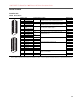
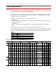
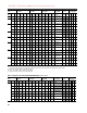
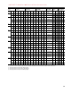
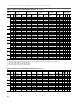
11 450 2 30.5 (100) 68.6 (225) 76.2 (250) 121.9 (400) 243.8 (800) 304.8 (1000)
1321-3R600-C
20 945
(3)
500 2 30.5 (100) 68.6 (225) 76.2 (250) 121.9 (400) 243.8 (800) 304.8 (1000)
1321-3R600-C
20 945
(3)
560 2 30.5 (100) 68.6 (225) 61.0 (200) 91.4 (300) 243.8 (800) 304.8 (1000)
1321-3R750-C
20 945
(3)
12
(1)
630 2 30.5 (100) 68.6 (225) 61.0 (200) 91.4 (300) 243.8 (800) 304.8 (1000)
2 X 1321-3RB400-C
40 480
(3)
710 2 30.5 (100) 68.6 (225) 61.0 (200) 91.4 (300) 243.8 (800) 304.8 (1000)
2 X 1321-3R500-C
40 645
(4)
800 2 30.5 (100) 68.6 (225) 61.0 (200) 91.4 (300) 243.8 (800) 304.8 (1000)
2 X 1321-3R500-C
40 645
(4)
13 900
(2)
2 30.5 (100) 68.6 (225) 61.0 (200) 91.4 (300) 243.8 (800) 304.8 (1000)
2 X 1321-3R600-C
40 645
(4)
1000
(2)
2 30.5 (100) 68.6 (225) 48.8 (160) 91.4 (300) 243.8 (800) 304.8 (1000)
2 X 1321-3R600-C
20 840
(5)
1100
(2)
2 30.5 (100) 68.6 (225) 48.8 (160) 91.4 (300) 243.8 (800) 304.8 (1000)
2 X 1321-3R750-C
20 840
(5)
(1)
Frame 12 drives have dual inverters and require two output reactors. The resistor ratings are per phase values for each reactor.
(2)
Some Frame 13 drives require two output reactors to match drive amp rating. The resistor ratings are per phase values for each reactor.
(3)
Resistor specification is based on two cables per phase.
(4)
Resistor specification is based on three cables per phase.
(5)
Resistor specification is based on four cables per phase.
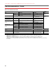
Drive No Solution Reactor Only Reactor + Damping Resistor Reactor Resistor Available Options
Frame kW kHz 1850V 2000V 1850V 2000V 1850V 2000V Cat. No. Ohms Watts
TFA1
TFB2
RWR2
RWC