
Manual

1336 FORCE™ To PowerFlex® 700S Phase II AC Drive Conversion Guide
32
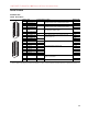
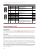
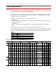
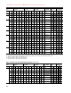
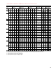
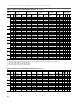
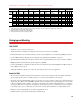
Table E TB2 Terminals
Cable Recommendations - Power
Unshielded Cable
THHN, THWN or similar wire is acceptable for drive installation in dry environments provided adequate free air space
and/or conduit fill rates limits are provided. Do not use THHN or similarly coated wire in wet areas. Any wire chosen
must have a minimum insulation thickness of 15 Mils and should not have large variations in insulation concentricity.
Shielded Cable
Shielded cable contains all of the general benefits of multi-conductor cable with the added benefit of a copper braided
shield that can contain much of the noise generated by a typical AC Drive. Strong consideration for shielded cable should
be given in installations with sensitive equipment such as weigh scales, capacitive proximity switches and other devices
that may be affected by electrical noise in the distribution system. Applications with large numbers of drives in a similar
location, imposed EMC regulations or a high degree of communications/ networking are also good candidates for shielded
cable.
Shielded cable may also help reduce shaft voltage and induced bearing currents for some applications. In addition, the
increased impedance of shielded cable may help extend the distance that the motor can be located from the drive without
the addition of motor protective devices such as terminator networks. Refer to “Reflected Wave” in publication DRIVES-
IN001…, Wiring and Grounding Guidelines for Pulse Width Modulated (PWM) AC Drives.
Consideration should be given to all of the general specifications dictated by the environment of the installation, including
temperature, flexibility, moisture characteristics and chemical resistance. In addition, a braided shield should be included
and be specified by the cable manufacturer as having coverage of at least 75%. An additional foil shield can greatly
improve noise containment.
Terminal Signal Factory Default Description Related Params
1 24V DC Common (-) NA Drive supplied 24V DC logic input power
Rating: 300 mA maximum load2 24V DC Source (+) NA
3 Digital Output 1 24V DC Open Collector (sinking logic)
Rating: Internal Source = 150 mA max.
External Source = 750 mA
846, 847
4 Digital Output 1/2 Com NA Common for Digital Output 1 & 2
5 Digital Output 2 24V DC Open Collector (sinking logic)
Rating: Internal Source = 150 mA max.
External Source = 750 mA
851, 852
6 Relay Output 3 (NC) Relay contact output
Rating: 115V AC or 24V DC = 2 A max.
Inductive/Resistive
856, 857
7 Relay Output 3 Com NA
8 Relay Output 3 (NO)
9 Digital Input 1-3 Com NA Common for Digital Inputs 1-3
10 Digital Input 1 High speed 12-24V DC sourcing Digital Input
Load:15 mA at 24V DC
825
11 Digital Input 2 826
12 Digital Input 3 Load:15 mA at 24V DC sourcing 827
13 Digital Input 4-6 Com NA Common for Digital Inputs 4-6
14 Digital Input 4 Load: 10 mA at 24V DC sinking/sourcing
Load: 7.5 mA at 115V AC
Note: The 115 VAC Digital Inputs can withstand 2 milliamps of
leakage current without turning on. If an output device has a leakage
current greater than 2 milliamps a burden resistor is required. A 68.1K
ohm resistor with a 0.5 watt rating should be used to keep the 115
VAC output below 2 milliamps.
828
15 Digital Input 5 829
16 Digital Input 6 HW Enable 830
1
2
3
4
5
6
7
8
9
10
11
12
13
14
15
16