
Manual

1336 FORCE™ To PowerFlex® 700S Phase II AC Drive Conversion Guide
31
Control Terminals
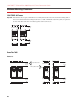
PowerFlex 700S
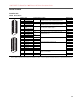
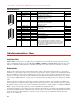
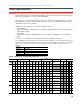
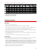
Table D TB1 Terminals
Terminal Signal Factory Default Description Related Params
1 Analog Input 1 Comm. (Volt) Bipolar, differential input, +/-10V, 0-20 mA, 13 bit + sign
20k Ohm impedance at Volt; 500 Ohm impedance at mA
(1)
(1)
The Analog inputs are not isolated. However, the analog inputs can be connected in series when using current mode. Note that at 20mA the voltage source
must be capable of providing 10V dc at the drive terminals for one drive - - 20V dc is required for two drives and 30V dc is required for three drives, etc.
2 Analog Input 1 (+/-) 800
3 Shield NA Analog Input Shield
4 Analog Input 2 Comm. (Volt) Bipolar, differential input, +/-10V, 0-20 mA, 13 bit + sign
20k Ohm impedance at Volt; 500 Ohm impedance at mA
(1)
5 Analog Input 2 (+/-) 806
6 Analog Input 3 [NTC-]
Comm.
(Volt) Differential input, 0-10V, 10 bit (for motor control mode FOC2, this
is the temperature adaptation input).
(1)
7 Analog Input 3 [NTC+] 812
8 Shield NA Analog Output Shield
9 Analog Output 1 (-) (Volt) Bipolar, differential output, +/-10V, 0-20 mA, 11 bit + sign
2k Ohm minimum load
832, 833
10 Analog Output 1 (+)
11 Analog Output 2 (-) (Volt) 839, 840
12 Analog Output 2 (+)
13 +10V Reference NA Rating: 20 mA maximum load (Recommend 5k Ohm pot)
14 Reference Common NA
15 -10V Reference NA
16 Encoder A NA Normal current draw per channel: 20 mA 230 - 234
17 Encoder A (Not) NA
18 Encoder B NA
19 Encoder B (Not) NA
20 Encoder Z NA
21 Encoder Z (Not) NA
22 Encoder Reference
(+)
NA 12 or 5V DC power supply for primary encoder interface
Rating: 300 mA maximum
23 Encoder Reference (-) NA
24 Encoder Shield NA Connection point for encoder shield
1
2
3
4
5
6
7
8
9
12
10
11
13
14
15
16
17
18
19
20
21
22
23
24