
Manual

1336 FORCE™ To PowerFlex® 700S Phase II AC Drive Conversion Guide
27
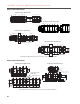
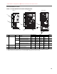
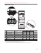
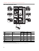
PowerFlex 700S - Frame 9
No. Name Frame Description
Wire Size Range
(1)
(1)
Maximum/minimum sizes that the terminal block will accept - these are not recommendations.
Torque Terminal
Bolt Size
(2)
(2)
Apply counter torque to the nut on the other side of terminations when tightening or loosening the terminal bolt in order to avoid damage to the terminal.
Maximum Minimum Maximum Recommended
1 Power Terminal Block 9
(3)
(3)
Do Not exceed maximum wire size. Parallel connections may be required.
Input Power — L1, L2, L3
Motor Connections — U/T1, V/T2, W/T3
185.0 mm
2
350 MCM
95.0 mm
2
4/0 AWG
40 N-m
(340 lb.-in.)
40 N-m
(340 lb.-in.)
—
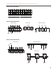
2 SHLD Terminal 9 Terminating point for wiring shields 95.0 mm
2
4/0 AWG
5.0 mm
2
10 AWG
22 N-m
(187 lb.-in.)
22 N-m
(187 lb.-in.)
—
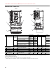
3 DC Bus
(2 Terminals)
9
(4)
(4)
DC terminal and brake lugs can be removed.
DC input or external brake
(Internal Brake option not
ordered)
185.0 mm
2
350 MCM
95.0 mm
2
4/0 AWG
40 N-m
(340 lb.-in.)
40 N-m
(340 lb.-in.)
—
DC Bus w/Brake
(3 Terminals)
9
(4)
DC input/internal brake
(Internal Brake option is
ordered)
185.0 mm
2
350 MCM
95.0 mm
2
4/0 AWG
40 N-m
(340 lb.-in.)
40 N-m
(340 lb.-in.)
—
4 Cable Clamp 9 Cable Clamp for Strain Relief —
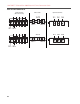
DC –
DC+/R+
R–
3
2
2
1
1
4